One thing i totally forgot to ask is how many volts do i need to have on the cap in the voltage divider (100uF) -The nichicon muse KZ i used before was 25V. I also have some some Cerafine and vishay/BC that are rated at 35V and 63V. Is that enough?
Does the quality of this cap matter?
Thx
Does the quality of this cap matter?
Thx
Is there any formula or anyway to know for sure how big output cap i really need? Is it gonna hurt to have to big value?
In comparison with my Yamaha i feel my tube pre still lack some lowbass, say under 40hz?! With 1,5uf. I've read somewhere it depends on output/input impedance? I'm driving a kt88 amp that has 12ax7, 6sn7gt and kt88's. If that makes any difference.
I don't wanna order some 50-60 bucks supercaps and later find out they are to small or to big..
Thx,
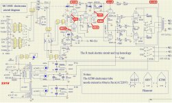
Here is the schematics of my poweramp, Yaqin MC100b.
According to technical data online i saw it has a input imp of 20k. BUT the volumepot is removed - I use it as a poweramp only. I don't know what that do to the input imp... So it only uses the "0.6V" input now.
EDIT: Also the switch is gone. The signal goes straight into each 12ax7!
According to technical data online i saw it has a input imp of 20k. BUT the volumepot is removed - I use it as a poweramp only. I don't know what that do to the input imp...
So it only uses the "0.6V" input now.EDIT: Also the switch is gone. The signal goes straight into each 12ax7!
Last edited:
I mean your actual preamp circuit, only to see why you lost bass.
With 1.5 μF and 1 MΩ to ground your frequency roll off is at about 3 Hz.
Ohhh ok. No cap on input, only 1M to ground. Output has 1,5uf and 100k to ground when i listened last time before pt burned up.
-I'm still waiting for my solder tin, without it i can't do much... I'm just preparing
been listening but only to my old yamaha pre and can feel it have more lowbass but also not as correct or tight as my srpp. But mid n high is so much better with my srpp maybe i just take the yamahas "slower" bass as deeper. Can be. How much is 1M vs 100k affect res.curve?
The volympot in my kt88 was just as techdata said, 20k too. I thought that decided "total" impedance and it would be different now when signal goes straight to 12ax7's. Or?
Ohhh ok. No cap on input, only 1M to ground. Output has 1,5uf and 100k to ground when i listened last time before pt burned up.
Need to know what you did with cathode resistors/LED/caps, a circuit would be more helping.
How much is 1M vs 100k affect res.curve?
From 0.1 Hz with 1.5 μF and 1 MΩ to 1 Hz with 1.5 μF and 100 KΩ.
Without volume pot, your amp has an input impedance of about 39 KΩ, so not much difference between 1MΩ and 100 KΩ, as I said before a frequency roll off at about 3 Hz.
Last time i listened it was a red led (very good sound) but i got a tip that two of this diodes in series was even better and and don't need to see that red light
I have 4 of them home right now. Voltage drop together of about 1,7V i was told.
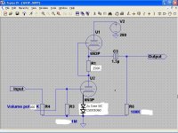
I Copied your schematics you drew (very professional) and tried to change how it's gonna look.
EDIT: The 250R is not maybe 100% correct, i have to measure voltagedrop i guess in final build but with red led vs 330R it was not equal at least. 5.3mA vs 4,7mA. I don't know exactly how it's gonna look with this new "diodes" but what i understood from you guys here both halves of tube have to be "balanced". Equal amount of current draw i mean.
I have 4 of them home right now. Voltage drop together of about 1,7V i was told.
I Copied your schematics you drew (very professional) and tried to change how it's gonna look.
EDIT: The 250R is not maybe 100% correct, i have to measure voltagedrop i guess in final build but with red led vs 330R it was not equal at least. 5.3mA vs 4,7mA. I don't know exactly how it's gonna look with this new "diodes" but what i understood from you guys here both halves of tube have to be "balanced". Equal amount of current draw i mean.
Attachments
Last edited:
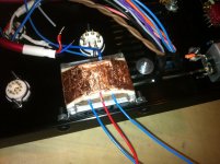
I have now all new components for my build except 6n3P tubes. New 400V caps , New pt as i showed, new rectifier and so on so i guess that (or really hope) that my previous problem with a burning pt is goone. I really don't know what went wrong.
If everything works out ok with this russian 6u5c i will change rectifier to a 5V4-G or a GZ32. Pt have a tap for 5V filament. Yes, mostly because of looks Like ST bottle tube =) IF anybody think it won't work (for some reason please tell)
Some datasheets info if somebody is interested:
5V4-G : http://www.r-type.org/exhib/aaa0597.htm
GZ32 : http://www.r-type.org/exhib/aad0204.htm
If everything works out ok with this russian 6u5c i will change rectifier to a 5V4-G or a GZ32. Pt have a tap for 5V filament. Yes, mostly because of looks
Like ST bottle tube =) IF anybody think it won't work (for some reason please tell)Some datasheets info if somebody is interested:
5V4-G : http://www.r-type.org/exhib/aaa0597.htm
GZ32 : http://www.r-type.org/exhib/aad0204.htm
Last edited:
Your preamp now looks very good and difficult to improve even more, and I don't see anything that could affect low end frequency response, except RC output filter, that as I said before has a very low frequency roll off.
As at low frequencies need more energy, could postulate the possibility that your PSU does not give enough energy, which is unlikely because this would translate to a higher ripple, and a simple line preamp doesn't need a power plant.
Maybe your amp OPTs are the culprits, for good bass response you need a big core or a lot of windings, and many manufacturers are stingy to give at least one of them, and perhaps your SS preamp has a bump at low end that mask it a bit.
Your preamp now looks very good and difficult to improve even more, and I don't see anything that could affect low end frequency response, except RC output filter, that as I said before has a very low frequency roll off.
As at low frequencies need more energy, could postulate the possibility that your PSU does not give enough energy, which is unlikely because this would translate to a higher ripple, and a simple line preamp doesn't need a power plant.
Maybe your amp OPTs are the culprits, for good bass response you need a big core or a lot of windings, and many manufacturers are stingy to give at least one of them, and perhaps your SS preamp has a bump at low end that mask it a bit.
You're probably right, it can be that my SS preamp has a "bump" that make bass a bit "fat".
I use my kt88 only over 180hz. I have an SS amp (american audio vpl-1500) to power subs with active crossover. (DCX2496) My speakers are almost fullrange having a -8db /22Hz and -3db by 27Hz.
How would freq.response be with a 1uF? (even cheaper for me and takes up less space?
How would freq.response be with a 1uF? (even cheaper for me and takes up less space?
Hey, what happened with cap rolling?
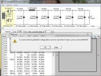
Seriously speaking, with 1 μF frequency roll off would be at about 6 Hz.
Hint
fo = 1/(2πRC)
As I have many old 1.5 μF Siemens MKPs I use to design with that value.
Edit: With 20K input impedance, and 1.5 μF with 100K, fo is about 6 Hz
R in equation above is R=100k//20K≈16.7K
Last edited:
- Status
- This old topic is closed. If you want to reopen this topic, contact a moderator using the "Report Post" button.
- Home
- Amplifiers
- Tubes / Valves
- My first preamp with tubes