I hadn't seen the link, I admit that I don't quite understand their explanation. They basically explain that a voltage regulator should not be too stable, right?
It's also for me not exactly clear, but it seems to me that they describe what we see with the Naim regulator. Basically voltage sags a little when high current flows. On the other hand I also can't imagine how voltage could stay on the exact same level when suddenly high current is to be delivered. So it somehow makes sense I would say, but again I don't really understand. Our scope shots show both: the little saw spikes and the droop sag, I guess that means they are well balanced in this regard...
i'm waiting now for new components i will test this week end if with New capacitors with hight esr in C101/102 it's even better for the supply stability because it's decoupling capacitors too.
then I could finally switch to my last amp to make the appropriate modifications
then I could finally switch to my last amp to make the appropriate modifications
So I received my new capacitors with higher esr. The 10 uf are around 1.8 ohms so lower than what I thought when ordering them (they were given for 4 ohms)
The 47 uf are at 0.4 ohms (they were given for 1 ohms)
After the ESR varies a lot depending on the frequency so it all depends on how it is measured...
So I tested these new capacitors fortunately the oscillation does not reappear with those! (since before I had caps at 2.6 ohms)
So I tested with the 47 Uf changed to 0.4 ohms of ESR (against 0.04 ohms before)
In the test, this does not seem to improve things much, so it is the output capacitor that are important at ESR level, here is the result:
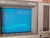
here it's a 100mvolts 1000hz signal on 6,8 ohms load with 1uf capacitor in parallel
The test at 1,8 volts 1000 hz in input (without the capacitor !) are ok no phase problem
So i finish to modify my old Amp now i will modify the last amp.
The 47 uf are at 0.4 ohms (they were given for 1 ohms)
After the ESR varies a lot depending on the frequency so it all depends on how it is measured...
So I tested these new capacitors fortunately the oscillation does not reappear with those! (since before I had caps at 2.6 ohms)
So I tested with the 47 Uf changed to 0.4 ohms of ESR (against 0.04 ohms before)
In the test, this does not seem to improve things much, so it is the output capacitor that are important at ESR level, here is the result:


here it's a 100mvolts 1000hz signal on 6,8 ohms load with 1uf capacitor in parallel
The test at 1,8 volts 1000 hz in input (without the capacitor !) are ok no phase problem
So i finish to modify my old Amp now i will modify the last amp.
Yesterday I attacked the modifications on the new amplifier and I had the bad surprise to note that the values that I had found for the phase compensation with my test board for the 2N6341 do not work!
It is however almost entirely the same amplifier with the same components ...
I still found a stable combination by modifying R26-R27-R29 and R30! up to 1.8 volts input. But on the other hand I find more distortion than with my test board I will try to change C6 in input for a 330pf because it is the value that I had on the test plate. The new version of the amp is actually sensitive as soon as I move the power supply wires more than with the other plate, it's quite curious. the only different value is the C6 which is 470pf on the new amp
Sensitive in what way...? Hum? Did you reroute the layout for the final amp? There are some sensitive points on the PCB, but all together it seems the layout is not extremely critical with this circuit...
This is another subject. But, I interested. did you measure the offset? it's interesting that my offset was positive, +20-30mv. So, I decreased hfe of tr1. Now tr1 is much less than tr2. In the forum always says that tr2 hfe must be %10 less than tr1.
Result -2mv offset. tr1 hfe is 500, tr2 greater than 600 🙂 Sound may be better, not sure. for the same reason MPSA06's emittor resistor is 680ohm not 620 or 560.
Result -2mv offset. tr1 hfe is 500, tr2 greater than 600 🙂 Sound may be better, not sure. for the same reason MPSA06's emittor resistor is 680ohm not 620 or 560.
Yes, it seems that the 10% hfe is not really original Naim idea. iirc Naim changed the value of that resistor at the collector of the MPSA06, I got best DC offset with 620R and matched LTP transistors. BTW the base trace of TR2 is a bit sensitive, so maybe better to keep it as short as possible...
Yes on the new design it is more sensitive when the phase compensation is not adjusted it varies according to the position of the power cables. This is how at the start just by twinsting the power cables by plugging my remote laboratory power supply into another socket I no longer had the phase problem which appeared at low power (100mV)
I had not against not tested at high power but it is possible that it should appear then. On the old design, the positioning of the wires does not have this impact.
I haven't tested yet by changing C6 to 330pf I haven't had time but we'll see what happens. It's the only value that differs from the previous tests I've done. If that doesn't fix things then that means it's the PCB routing and power transistor wiring that changes things.
For the offset respecting the design of NAIM I always had good offset lower than 10mv by having a perfect pairing of the LTP.
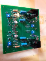
I attach my actual layout (all tracks are on the backside except the blue ones). Note the red marked areas: ground arrangement of the input network, base of TR2, copper areas for heat sinking of the ZTX transistors, connecting point of the feedback line, current flow of the output resistors. The jumpers at the drivers are there because pinout of 243/253 is different from 15030/31...
Attachments
I did the test by changing C6 it changes things a little bit but not much in fact
so it's the routing that changes the game....
I found better values than before and the amp is even more stable on capacitive load and more good on distorsions so I think it's not bad but I have to exceed 2100 ohms and my variable resistors do not go beyond to stabilize at more than 1 volts so I will have to order other resistors again to finish the adjustment but I think I will be able to adjust it with the least amount of distortion visible on the oscilloscope.
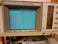
here is the test on capacitive load 1Uf with my previous values:
Here is the same test with the last values tested:
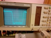
In conclusion, depending on the power transistors used, the phase compensation may need to be developed for each routing, in any case with the 2N6341 it is very sensitive.
on the routing of my amp the distance between the LTP and the ZTX is important but the one with the miller capacity is lower I think it may be that compared to the old design.
On my last file 2.4 it is much shorter
so it's the routing that changes the game....
I found better values than before and the amp is even more stable on capacitive load and more good on distorsions so I think it's not bad but I have to exceed 2100 ohms and my variable resistors do not go beyond to stabilize at more than 1 volts so I will have to order other resistors again to finish the adjustment but I think I will be able to adjust it with the least amount of distortion visible on the oscilloscope.
here is the test on capacitive load 1Uf with my previous values:

Here is the same test with the last values tested:

In conclusion, depending on the power transistors used, the phase compensation may need to be developed for each routing, in any case with the 2N6341 it is very sensitive.
on the routing of my amp the distance between the LTP and the ZTX is important but the one with the miller capacity is lower I think it may be that compared to the old design.
On my last file 2.4 it is much shorter
C6 (feedback cap.) quality is very important in that circuit. After all, for sensitive adjustment.
Looks good! I will change my layout and put the input pin a bit away from the power rail, and also get more space between the LTP and the ZTX...
Yes it seems much more stable with this setting or with this value of C6? (330pf instead of 470pf)
Why would you want to keep the ZTX away? on the original naim design it is quite close to the LTP
For the power rail, I'm actually following you, it's better to move it away.
In any case I realize that the PCB layout is more important than i expected. It must be admitted that on this 2n6341 getting the right setting is not easy! It is sure that the MJ15003 are much easier to use
I had made some errors on the one I use in my amp I redid a last version 2.5 I think it is better but on the other hand I could not give the right values for the phase compensation it will be necessary for those who would like to use it make the adjustment themselves.
Honestly I don't know! I simply note that on the NAIM design and on my old design (for which I had copied the PCB layout as much as possible) the ZTX is close to the LTP. I just wanted to understand where the differences that I observe on the phase compensation setting come from, is it the PCB layout that must change things, maybe the track lengths? After tuning are different is not so much of a problem if the amp works as well and sounds the same.
You just have to know that it differs according to the PCB used.
I think your PCB layout is fine if the amplifier works well like that I'm not sure changing it will do much.
I'm just surprised that the PCB layout has such an impact on adjusting the phase of the feedback mouth
The values I used on the first photo are:
C6 470pf
R26 1240
R27 1180
R29 1830
R30 2120
With that the amp is stable up to 1.8 volts without worries but I have more distortion than what I was able to obtain on my old design
So I tried to get a better combination here:
C6 330pf
R26 1640
R27 1640
R29 2080
R30 2120
We see with this one I have much more stability and less distortion on the other hand I cannot go up beyond 800 mvolts and I know that it would be necessary to increase R29 and R30 even more to obtain this stability at high voltage but my variable resistors are 2Kohms so I have to recommend parts
But first I would like to test as it is in the amplifier to check that with the 39.2 volts / -39.8 Volts this does not modify the phase setting
I had fun lowering the voltage of the laboratory power supply to 24 volts and that does not modify anything so I think and I hope that the phase compensation does not depend on the supply voltage.
Then I would order parts including variable resistors at 3Kohms to determine the values of R29 and R30.
In any case the setting of this amp with the 2N6341 is longer and more delicate than what I expected! but I think I'm close to the goal.
note I was wrong when I spoke of the C6 capacitor in fact I was talking about C8
I did a lot of testing today. So in the amplifier directly I will use the following values:
C8 470pf
R26 1800 ohm
R27 1800 ohm
R29 2200 ohm
R30 2200 ohm
I did tests directly in the amplifier and the higher voltages do not seem to change the situation. I tested under 6.8 ohms from 100 hz to 30,000 hz under 100 mvolts to 1 volt input and everything is fine.
I also tested at 1000 hz and 10,000 hz at 6.8 ohms up to 2 volts input and no worries, it's stable
I tested the stability with the load of 1 uf and it is a little worse than what I had in test before but it is still good
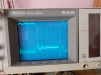
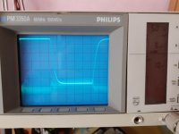
the power rails are ok and don't oscillate with the new capacitors
I also tested under loads of 2 Ohms and at 14 ohms up to 1 volt input from 100 hz to 20,000 hz I did not detect any problems
finally I also tested at low power from 10 mv to 100 mv I did not detect any problem either
I then did a listening test comparing it with the other channel and it's very good, I even think it's a little better with the modifications.
Anyway, I think I've finished the development.
tomorrow i have a big day of work but on tuesday i think i can finish the modifications of the amplifier
currently i am using my old amp in my chain and i think it is better than before with the modifications made.
I did a lot of testing today. So in the amplifier directly I will use the following values:
C8 470pf
R26 1800 ohm
R27 1800 ohm
R29 2200 ohm
R30 2200 ohm
I did tests directly in the amplifier and the higher voltages do not seem to change the situation. I tested under 6.8 ohms from 100 hz to 30,000 hz under 100 mvolts to 1 volt input and everything is fine.
I also tested at 1000 hz and 10,000 hz at 6.8 ohms up to 2 volts input and no worries, it's stable
I tested the stability with the load of 1 uf and it is a little worse than what I had in test before but it is still good


the power rails are ok and don't oscillate with the new capacitors
I also tested under loads of 2 Ohms and at 14 ohms up to 1 volt input from 100 hz to 20,000 hz I did not detect any problems
finally I also tested at low power from 10 mv to 100 mv I did not detect any problem either
I then did a listening test comparing it with the other channel and it's very good, I even think it's a little better with the modifications.
Anyway, I think I've finished the development.
tomorrow i have a big day of work but on tuesday i think i can finish the modifications of the amplifier
currently i am using my old amp in my chain and i think it is better than before with the modifications made.
Great ! Don't forget to show us the photos!
I finished the right channel, now I'm attacking the left channel ^^
I finished the right channel, now I'm attacking the left channel ^^
- Home
- Amplifiers
- Solid State
- NAIM NAP250 Original clone build thread
