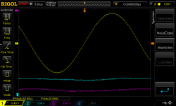
Here a comparison between regulated and raw power supply. The regulator is Jeff's inverted design which looks really similar to the raw supply. The original Naim regulator provides slightly flatter power rails (see previous shots):
Attachments

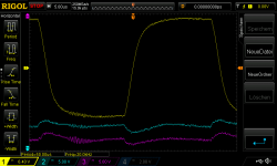
You can see some instability also in my previous scope shots in the supply rails, even the Naim regulator board shoes this. But only at high power into a 8R/1uF load with square wave - really brutal, I even smoked one of my regulator boards yesterday (and repaired it already).
PSU is 500VA with 22.000uF. What do you think of the supply rails moving slightly up and down with the sine waves? Is that a bad thing?
PSU is 500VA with 22.000uF. What do you think of the supply rails moving slightly up and down with the sine waves? Is that a bad thing?
Last edited:
")
I'm a little surprised because for me the Mj15024 sound pretty good.I heard the 6341 is not easy to use in an audio amplifier, and also the 15024 sometimes does not sound natural in the mids: can you describe in what way they sound better than the 15003?
With the Mj15003 the sound in the treble is quite dry and a little aggressive; it's analytically detailed but less natural than with the MJ15024 or the 2N6341. On the timbres of the instruments in particular, the piano or the voices are more natural, in short it is better for me with these transistors than with the Mj15003.
As for the tests on capacitive load of 1Uf, doing it at a very high level and over a long period is actually dangerous for the circuits. It is advisable to do it over a short period, I put in contact over a short period of time and I do not test at such a high level. I went high to see the high level phase faults but for stability on capacitive load it's better not to do that.
You just have 1 volts in the output of the amp to test stability on capacitive load.
i read the trick on this site:
https://www.astuces-pratiques.fr/electronique/ampli-audio-stabilite-et-oscillations
Interesting! Yes, the 15003 tends a bit to the bright side compared to the Naim board (the Naim amp board sounds a bit nosy and dull in comparison I thought).
Testing regulated vs. raw at the power stage it seems to me that the raw supply sounds more voicy, cleaner, and bouncier than regulated, but regulated sounds more tidy and also tighter. Adding regulation to the front end made a huge difference: with the raw supply at the power stage the super reg was the best out of the 3 at the front end (super reg, Naim reg, Jeff's inverted reg). With the super reg at the front end and the Naim reg at the power stage the music came really to sing, that was a huge difference in quality. Taking away the regulation from the power stage reduced everything by a significant step. BTW Jeff's inverted reg always sounded slightly brighter and tighter than the Naim reg.
So the results are a bit confusing, but I will try again tomorrow. For now I can say that the front end sounds better with regulation in all cases. But I can't say if with regulated front end the power stage also "needs" regulation for best performance. It seems yes, but I will do more tests...
Last edited:
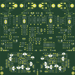
Separate PSUs for front end and output stage make big differences, plus the differences between PSU caps are huge! Tested Mundorf, Kemet, CDE, some of them CRC, some CC (2 in parallel), etc. etc., big big differences - the wrong combination can ruin the hole setup quite easily. Best so far were separate Kemet slit foils both at front end and power stage. CRC slows down things considerably, so link out the R and just let the amp suck directly at the caps. Here my attempt of a combined PCB for a full regulated mono amp - it has the mentioned super reg for the front end and the Naim reg for the power stage (one with Jeff's inverted version will follow):
Attachments
Nice solder jointsHello here is progress of the project. unfortunately I'm not moving fast, I must say that I'm very busy with my work these days.
I finished and tested the second regulation board
then i cleaned the solder flux from all four boards.
View attachment 1106531
View attachment 1106533
View attachment 1106534
I received the final box
View attachment 1106526 View attachment 1106527
and I mounted the cards on the two heatsinks of the box and it was not without difficulties but finally we got there.
View attachment 1106529 View attachment 1106528 View attachment 1106530 View attachment 1106532 View attachment 1106525
Ty jean 01
Naim has also worked on the regulation with its DR system to improve its amplifier and your PCB will look a bit like theirs even if it seems to me that the DR system remains a single regulation for the entire amplification circuit.
Being quite busy with my job and the family I couldn't advance the tests this weekend but I should be able to advance tonight I hope.
It's a very interesting mod. you put regulated PSU on the same PCB like naim does in NAP 250.2 DR.Separate PSUs for front end and output stage make big differences, plus the differences between PSU caps are huge! Tested Mundorf, Kemet, CDE, some of them CRC, some CC (2 in parallel), etc. etc., big big differences - the wrong combination can ruin the hole setup quite easily. Best so far were separate Kemet slit foils both at front end and power stage. CRC slows down things considerably, so link out the R and just let the amp suck directly at the caps. Here my attempt of a combined PCB for a full regulated mono amp - it has the mentioned super reg for the front end and the Naim reg for the power stage (one with Jeff's inverted version will follow):
Naim has also worked on the regulation with its DR system to improve its amplifier and your PCB will look a bit like theirs even if it seems to me that the DR system remains a single regulation for the entire amplification circuit.
Being quite busy with my job and the family I couldn't advance the tests this weekend but I should be able to advance tonight I hope.
Yes: I did further tests, and they confirm what Naim does is good for their amp circuit. So, best I found for now is separate traffos for front end and power stage for each channel, with 100nF caps across the rectifier diodes, Kemet slit foil cap banks for the power stage, separate regulation for front end and power stage. When sharing traffos for both channels at least keep separate rectifiers and caps for each regulator. Using one traffo per channel sounds more separate, using one traffo for the front ends and one for both power stages sounds cleaner, but 4 traffos are best.
BTW as you noticed there was a slightly sharp tendency by the MJ15003s (especially with Jeff's inverted regulator), but once you get the power right, it all blends nicely into a really smooth, clean and open top end: I found that Mundorf caps for the front end (CRC) helped in that regard and gave the icing on the cake.
BTW as you noticed there was a slightly sharp tendency by the MJ15003s (especially with Jeff's inverted regulator), but once you get the power right, it all blends nicely into a really smooth, clean and open top end: I found that Mundorf caps for the front end (CRC) helped in that regard and gave the icing on the cake.
I continued the tests the day before yesterday. I tested with the Mj15003 once the phase compensation was adjusted with different frequencies and impedances (14Ohms, 6.8ohm, 4ohms at 100Hz, 1000Hz, 10,000Hz and 20,000Hz)
And the amp reacts the same up to 1 volt input, in short, the phase problems do not seem to depend on the impedance of the load or the frequency of the signal.
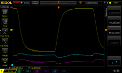
I then started the tests on the 2N6341G I was able to adjust the phase compensation, it reacts well I went up to 1.7 volts input on 6.8ohm. It is stable with a test on the capacitance of 1 Uf.
On the other hand there is more crossover distortion than with the Mj15003, it appears a little beyond 20,000Hz So it's better than with the BUV22 or the MJ15024 but not ideal either. Maybe other drivers should be ideal, I don't know.
I still have to confirm these tests with different frequencies and impedance. after I will try another transistor for TR5 (ZTX690B)
Then I would retest the stability of the regulation card.
results on 2N6341G at 10Khz/100mv 6,8ohms, 1Uf capacitor


And the amp reacts the same up to 1 volt input, in short, the phase problems do not seem to depend on the impedance of the load or the frequency of the signal.
I then started the tests on the 2N6341G I was able to adjust the phase compensation, it reacts well I went up to 1.7 volts input on 6.8ohm. It is stable with a test on the capacitance of 1 Uf.
On the other hand there is more crossover distortion than with the Mj15003, it appears a little beyond 20,000Hz So it's better than with the BUV22 or the MJ15024 but not ideal either. Maybe other drivers should be ideal, I don't know.
I still have to confirm these tests with different frequencies and impedance. after I will try another transistor for TR5 (ZTX690B)
Then I would retest the stability of the regulation card.
results on 2N6341G at 10Khz/100mv 6,8ohms, 1Uf capacitor
M
maybe ! but i don't have this drivers for now to test it ! i have another reference in stock i have to look at the datasheet of this first ^^Great! Maybe the MJ15030-33 as drivers solve the cross over problems, Avondale uses them even with 15003s, and many other clones do as well.
mdardeniz with 100 ohms ? what resistors you tell about ?
Sound signal is not a unique frequency. it depends on some harmonics and some addition of different frequencies. for example 20khz signal on the 1khz sin signal. I'm writing that, I want to find some complex signals for ltspice to simulate sound waves. Perhaps, someone show a PWL file or any advice? Is this another thread head?
I have completed the tests on the amplifier board. With the 2n6341G I get the following values:
R25 2000 ohms
R26 1000 ohm
R27 750 ohm
R29 680 ohm
R30 820ohms
Crossover distortion appears around 30,000 hz
I did a listening test the amp sounds good it doesn't seem to really change the sound.
I can go up to 1.8 volts at the input so I'm quite happy with the result on this transistor model.
For the Mj15003 I found the following values (which are not claimed the very best)
R25:2000
R26 470
R27 150
R29,680
R30 220
in fact there is only R30 to change
with these values I go up to 1.5 volts in input
All these tests are done on 31 volts in power supply, so I tested at 24 volts to see if the supply voltage had an influence this does not seem to be the case I hope that on my final amp I would not see the worries reappear with the stronger tensions.
I have started doing some tests on the regulation board so far I don't see any obvious problem but I'm just getting started. a fun pick is that the amplifier is more stable on capacitive load when powered from the regulation board the oscillation is much lower and better damped which isn't a bad thing!
I said before I had a problem with mje243/53. They were from aliexpress. Now I bought them from RSonline. I changed MJE15030/31 with MJE243/45. There is no any problem now. The result is looking like the same. If any difference in sound I will write here. Only necessary Bias voltage decreased.
- Home
- Amplifiers
- Solid State
- NAIM NAP250 Original clone build thread