I continued my tests with the Mj15024, suddenly I also tested different values on R30 (390 ohms base) because on some NAIM it is at 220 ohms or 180 but the results are not as good as using the values 680/560 on R26/27.
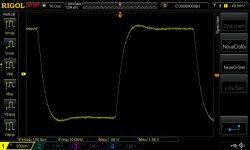
On the other hand, by leaving R25 at 2200 ohms, I have this when I test the stability with a capacitance of 1Uf in parallel on the load:

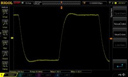
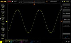
So by putting a 2000ohms back and put the bias good it's much better and I also tested on a 4 ohm load:

So for the moment with the MJ15024 the best values seem to be R26 680 R27 560 and R25 2000 ohms.
Here I am just starting tests on the BUV22
On the other hand, by leaving R25 at 2200 ohms, I have this when I test the stability with a capacitance of 1Uf in parallel on the load:
So by putting a 2000ohms back and put the bias good it's much better and I also tested on a 4 ohm load:
So for the moment with the MJ15024 the best values seem to be R26 680 R27 560 and R25 2000 ohms.
Here I am just starting tests on the BUV22
I don't know, I work very empirically! from what naim was doing
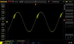
I note for the moment that the BUV22 seems to require a strong quiescent current so as not to have visible crossover distortion on the oscilloscope beyond 10Khz
On the other hand, it behaves rather well in terms of phase compensation with the original values. I still have to do other tests with lower loads too and adjust things ^^ But it's the level of crossover distortion with the original naim bias that made me eliminate this transistor as a candidate I don't know if you can run the amp with a much higher level of bias without risk.
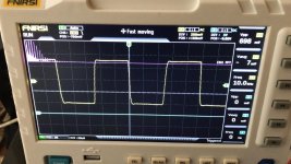
cristobool, what was the frequency of square wave of that oscilloscope pictures?
the BUV22 seems to require a strong quiescent current so as not to have visible crossover distortion on the oscilloscope beyond 10Khz
Can you post a picture of this? I would like to test the same with the BUV21. BTW old datasheets do not mention the BUV21 being a dalington, only Onsemi shows such a diagram - what do you think...?
It's a 10 000 Hz square wave 100mv signal at input with a 1 uF capacitor in parallel on 4 Ohms loadcristobool, what was the frequency of square wave of that oscilloscope pictures?
as you can see if R25 is 2000 ohms the depreciation is more symetrical and much better.
FOr the BUV 22 ok i will try to put a picture of the crossover distorsion this evening after my work day . I d'ont know if it's a darlington i had the same problem this information is not always clear in the datasheets.
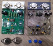
This is my 100mV/10kHz square wave output at the end of 7m speaker cable into 8R and 1uF, powered from a +/-32V bench power supply. MJ15003s driven by MJE243/53, genuine BC239Cs with HFE >500 in the LTP, resistor values 470/150 and 390/680 with R25 = 2K (R12 in my schematic).
Attachments
Here are the BUV21, they look good with 100mV input as well, but as soon as I go up to 300mV I get horrible instability. Cranking up the bias helps a bit, but only up to 500mV. The Naim stays clean up to 2V... Does this mean the MJE243/53 can't drive the BUV21s well?
Attachments
OK, fitted back the 15003s to my board, and tried various settings. It's really stable only with 470/140, 390/680 and R25 = 2K (R12 in my schematic) plus 22pF added to the exsting 39pF of C4 (C6 in my schematic). First I tried 44pF in C4, that was not enough, I still had some small oscillation at 2V input and 20kHz sine wave. Only with 39pF + 22pF in parallel the oscillation disappeared. The Naim is rock solid with 39pF. The BUV21s I coudn't get stable with the MJE243/53s, guess I will have to test with MJE15030/31...
Attachments
I am seeing exactly this kind of problem: it went away when I increased the miller cap. Is that a good solution?
For phase problems as I said above increasing the value of the miller improves things but it is not enough and it is not the most effective, modifying the values of the resistors in the compensation is good more efficient.
For R25 at 2200 ohms this changes the BIAS setting and as you saw above the amp is not stable enough with a badly damped oscillation on the negative part when you put a capacitor in parallel while with 2000 ohms the oscillations are well damped. On my test PCB, the output transistors are wired in the air, which lengthens the tracks significantly, which necessarily degrades the stability a little.
Afterwards I have not yet done any tests with strong input signals. 2 volts seems huge to me at the input, usually the amps accept a maximum of 1 volt, don't they?
I'm afraid that my transistors are not cool enough to do such tests.
Immediately I cannot load the photos I will try to load them this evening but the BUV22 for the moment react well on 2 ohms 4 ohms and 6.8 ohms with 100mv in input with the initial values in phase compensation (470/150 /2000 and 680/390)
On the other hand, there is visible crossover distortion around 30,000 Hz.
During my first tests more than 6 months ago I had a phase problem with the BUV22 but it seems to me that it was with a higher load at around 14 ohms.
- Home
- Amplifiers
- Solid State
- NAIM NAP250 Original clone build thread