I want to say, all NAP versions have different frequency compensation. Here, talking like all are the same??What's your aim in altering the frequency compensation of the design and adding new features? This may be interesting in a Naim mods or general design thread but it does seem OT in a thread specifically about Jeff's clone of the original NAP250 design.
That mode, HF resonans is about over heat of my NAP250 when idle. There is no orginal transistors, perhaps for that reason amp. resonans and I want to find a solution. Or can anybody build an original sound of Naim with that clones?
Your schematic in post 238 is not a NAP250. Lots of things are different, including a 1uH output inductor and 1uF load. That’s a 160kHz resonance right there. You’ve also got emitter resistors on your input LTP. You have basic regulation on the power supplies.I want to say, all NAP versions have different frequency compensation. Here, talking like all are the same??
That mode, HF resonans is about over heat of my NAP250 when idle. There is no orginal transistors, perhaps for that reason amp. resonans and I want to find a solution. Or can anybody build an original sound of Naim with that clones?
Forget C13. Do a frequency domain plot and see where the circuit gets excited. A spectral analysis is not the best tool for this. Make sure your output transistor idle current is about 50mA. Try adjusting the Miller cap and the phase lead compensation in the NFB path.
Guys,
Start with the transformer... and figure out how you twist your wires and do windings.... AC is the most important part here... less mistakes from AC creates more room for the amplifier boards.
EDIT:
I have just tested few more computer PSU with i5 2500(sandy) 8GB CREATIVE Audigy RX setup. My opinion is again changed about these "sound" cards we are pushed to use as a Source of "sound-quality". LMFAO
No, they are not the source at all... its the PSU that makes PC sound different to each-other. I have one unit that i like the most.
Conclusion - you can dumb&dump 1 ton of semiconductors and precious metals into a soundcard, it wont make a difference if PSU is not up to it.
These ferrite-iron-aluminum combo inductors on AC filtering line and at the output of a SWITCHMODE PSU is what determines the sound(harmonics).
Last edited:
Maybe its the 50hz and 60hz line frequency that is out of tune and is killing us all slowly causing cancer. I might think that USA has better chance of getting cancer cuz they run theyr lines faster.
Hmmm, solution would be to lower the f. range, to lower the chance of getting sick... up voltage a bit for more efficiency lol.
There is something wrong at the source lol and we making it worse and worse all the time.
Hmmm, solution would be to lower the f. range, to lower the chance of getting sick... up voltage a bit for more efficiency lol.
There is something wrong at the source lol and we making it worse and worse all the time.
As Ian Finch pointed out this design relies on switching transistors. The longer Ton and Toff is the longer the time delay whereas time has an inverse relationship with frequency so longer delays reduce the frequency response.
Also turn on and turn off arise in a zone where the transconductance plot is curved - that being between 0 volts to circa 0.6V . The shorter the distance along such a curved plot the more this will resemble a straight line. Negative feedback aids this diminutive process so this should be maximized as far as possible.
Frequency response is also due to the speed of the output transistors and MJ15003 devices have lower fT than 10MHz of BDY56 then the phase of the feedback will start to alter at a lower frequency.
re fT that is the point where transistor gain declines to one. That is well above the point where gain declines to 0.707 of that at 1Hz - i.e. -3dB. Phase starts to change a decade in frequency below the latter -3dB point.
Overall there are two sources of switching delays to master in order that the Vas reduces gain so reduces at a lower frequency so the stability margin is preserved - i.e. so this in step with the reductions if frequency mentioned.
Jeff has tried a two pole compensation scheme with MJ15003's - the original circuit is a finely tuned amplifier and I see this approach as an unnecessary compromise and complication when Futurlec a surplus parts supplier has 2N5038 devices switching types listed at bargain prices.
You could have a job to make this highly tuned circuit stable with a single dominant pole using MJ15003's.
Although it may be possible to make the circuit stable with a two pole compensation scheme for me there is a drawback with less upper high frequency nfb and I have strong doubts about this approach in emulating an NAP250 in terms of sound character.
I am in agreement with Ian Finch re approach if a suitable switching transistor can be sourced. I see Futurlec who deal in surplus components have 2N5038 switching transistors listed - these are in the same packaging as MJ15003 and they are going for a bargain price.
Also turn on and turn off arise in a zone where the transconductance plot is curved - that being between 0 volts to circa 0.6V . The shorter the distance along such a curved plot the more this will resemble a straight line. Negative feedback aids this diminutive process so this should be maximized as far as possible.
Frequency response is also due to the speed of the output transistors and MJ15003 devices have lower fT than 10MHz of BDY56 then the phase of the feedback will start to alter at a lower frequency.
re fT that is the point where transistor gain declines to one. That is well above the point where gain declines to 0.707 of that at 1Hz - i.e. -3dB. Phase starts to change a decade in frequency below the latter -3dB point.
Overall there are two sources of switching delays to master in order that the Vas reduces gain so reduces at a lower frequency so the stability margin is preserved - i.e. so this in step with the reductions if frequency mentioned.
Jeff has tried a two pole compensation scheme with MJ15003's - the original circuit is a finely tuned amplifier and I see this approach as an unnecessary compromise and complication when Futurlec a surplus parts supplier has 2N5038 devices switching types listed at bargain prices.
Ian Finch has pointed out the original design used switching transistors. Any time a device is off then the time delay has an impact on the negative feedback transition frequency. If the delays are summed then the total will have and inverse effect on frequency response and the potential will reduce.I'm looking at building a NAP250 clone. Since this will mostly be a nostalgia project, I'm trying to be fairly faithful to the original.
However, I won't have the volumes Naim did (for parts matching), and some parts production has since been moved to China (so I'm probably looking at greater variability to start with). The knife-edge stability of the original therefore has me a bit worried.
Here's something pretty dang faithful, but with the standard Miller compensation replaced by transitional Miller compensation (which seems appropriate as it was first proposed by Baxandall, who also has his diode in the quasi-complementary circuit):
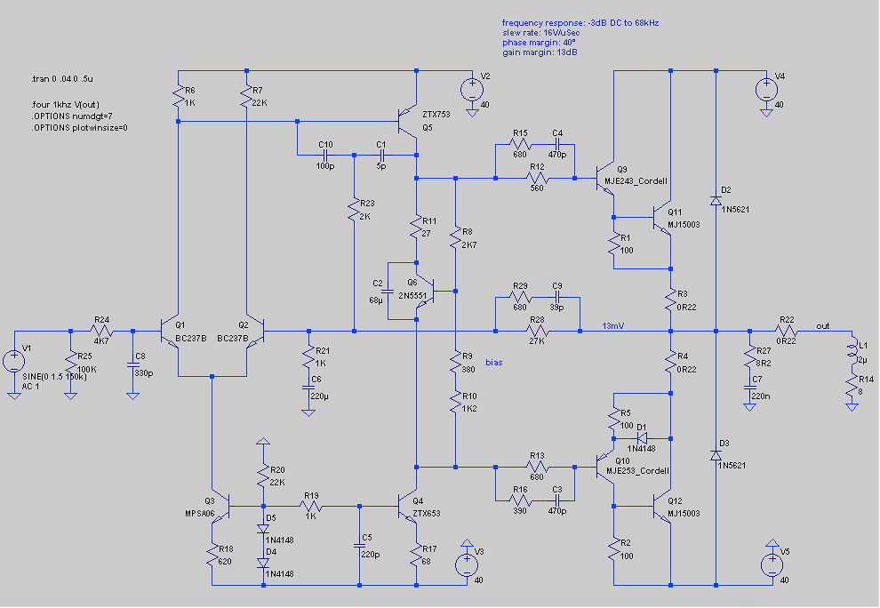
It serves its primary purpose of improving the stability without sacrificing the slew rate, although I couldn't get the stability up much without introducing a lot of distortion. So the phase margin is still, well, marginal. On the other hand, the slew rate has doubled, and the frequency response has improved considerably.
Any thoughts on this, including what it might do to the sound signature?
Thanks,
Jeff.
You could have a job to make this highly tuned circuit stable with a single dominant pole using MJ15003's.
Although it may be possible to make the circuit stable with a two pole compensation scheme for me there is a drawback with less upper high frequency nfb and I have strong doubts about this approach in emulating an NAP250 in terms of sound character.
I am in agreement with Ian Finch re approach if a suitable switching transistor can be sourced. I see Futurlec who deal in surplus components have 2N5038 switching transistors listed - these are in the same packaging as MJ15003 and they are going for a bargain price.
Semelab and their distributors come to mind for obsolete industrial and mil. spec types in the UK, though small qty prices can wind up being obscenely high. That's where BUV20 comes into the picture as a reliable substitute for BDY58. I think there would be SOA issues with 2N5038 as a substitute for that larger type in the NAP250 but I don't know much about the product and I've never seen it in a linear application. ISC or Inchange Semi's replacement types semis are quite reputable too - don't be fooled by association with other Chinese products sold by retail platform sellers.
DIYs probably feel more secure in buying from their local, traditional suppliers, who now offer generic house brand products but we probably don't realise that they're sourcing them from Chinese and other low-cost fabs anyway.
For fun facts; when SGS-Thomson were producing BDY56 and 58 long ago, datasheets showed side-by-side printed versions of the dies and they made no bones about the one being essentially a photo-enlargement of the other. 'nothing unusual there nowadays either, I imagine.
It would be nice if BUV20 was easy to get. Mainstream suppliers list them as obsolete or no longer in production.
The durability of the 2N5038 is less than the BUV20 but with some care it could be used in the NAP250 by changing the regulated supplies so these trip at a lower current level. This could be done by reducing a couple of 39pF capacitors or increasing the values of the series resistors in the supply rails.
The NAP250 was developed to handle heavy loads imposed by loudspeaker designs with complex crossover networks of the time aimed to even out frequency response. Nowadays with modern speaker drive units crossovers don't need to be so complex and impose less of a load on an amplifier.
Using MJ15003's is not a proper substitute for an amplifier designed with output devices having an fT of 10MHz since the voltage gain stage is compensated for a higher unity gain frequency than would apply with the 2MHz fT of MJ15003's.
In line with accepted science, to maintain the stability margins the voltage gain stage compensation capacitors need to be increased to suit the lower fT. That has not been done here. Loudspeakers can generate out of phase signals into the feedback line. Adding a coil is not going to mitigate against all potential ones arising getting through into the feedback path - messing with the stability and the sound.
The 2N5038 has a fT better than BUV20 and BDY56/58 so the original compensation scheme would stay in place.
Has anyone tried using Japanese horizontal output transistors here? They show up on the surplus market from time to time, and it’s a good bet they’re NOT fakes because nobody wants ‘em. Some types I’ve seen are even ring emitters. The Jap types have always had better SOA than 2N types pretty much across the board. The only downside I see is low hFE, but most fast switching types aren‘t very high and the normal drivers employed here are pretty robust. I had given up on using them years ago because they’re not strong enough or enough gain to use on 80 volt rails, but on only 40 volt rails the SOA may be just fine. Better than that 2N5038.
I've kept a small stash of TV power semis and other collectables gleaned from scrapped chassis but unfortunately, not enough to make up a foursome for a stereo amp and leave a few spares for likely problems. Some of these found their way into power supplies and experiments with class A which weren't spectacular but worth the effort to learn something about "unconventional" semi applications . I haven't ventured into AB amplifiers with anything but the usual audio types and of course, switching types for the Naim clones that I'm still fond of tinkering with. I think you're fortunate indeed in the US, to have a huge surplus market for semis to pick and choose from. Apart from North America and east Asian manufacturing centres, almost everywhere else puts a high price tag on power semis of all descriptions.
Yes, BUV20 semis are obsolete but you can buy what you need at reasonable prices (they were never particularly cheap, IIRC) from even ISO9001-9003 qualified sources. Because you also have the balanced, regulated power supplies to consider with this model, I'd budget for qty 12 minimum, even if I was feeling lucky. https://www.digipart.com/part/BUV20
Yes, BUV20 semis are obsolete but you can buy what you need at reasonable prices (they were never particularly cheap, IIRC) from even ISO9001-9003 qualified sources. Because you also have the balanced, regulated power supplies to consider with this model, I'd budget for qty 12 minimum, even if I was feeling lucky. https://www.digipart.com/part/BUV20
I have a few sets of Toshiba 2SB645 and 2SD665, high power transistors which are rated for switching applications, albeit the T on and T off figures are not included in the datasheets. The fT is though and quoted as 15MHz minimum for the 2SD665 which is a bit better than with the BUV20 and BDY56/58.
I have used these in power amplifier output stages and voltage regulators and found them to be reliable. There are plenty of datasheets online that one could examine for more detail. A little research for the real devices gave one hit for the NPN device - see https://www.newbecca.com/product/579382136597
I have used these in power amplifier output stages and voltage regulators and found them to be reliable. There are plenty of datasheets online that one could examine for more detail. A little research for the real devices gave one hit for the NPN device - see https://www.newbecca.com/product/579382136597
Certainly powerful brutes! The Cob is fairly high at 450 and 300pF respectively but I'm unsure how much this relates to switching times. For comparison, Onsemi linear audio power transistors like MJ15015 through MJ15025 have around 500pF Cob.
Switching takes place in a curved region of a transconductance plot however transistor data sheets have a lowest current starting point of 0.1 A so these are of no help.
One can get a little more information from .models particularly TF or Ideal forward transfer time for devices in SPICE libraries - and use with reference to http://www.signalpro.biz/wordpress/...the-transition-frequency-for-bipolar-devices/
One can get a little more information from .models particularly TF or Ideal forward transfer time for devices in SPICE libraries - and use with reference to http://www.signalpro.biz/wordpress/...the-transition-frequency-for-bipolar-devices/
Last edited:
Signalpro appear to be RF engineering heavyweights. Most of their links have problems with my VPN internet connection but at least I can access that link to their blog without having to sign up and join them - thanks. The subject matter isn't exactly new though, just seldom discussed in detail with reference to audio. It makes me wonder how JV cottoned on the notion of fast switching being the bigger deal he made it out to be rather than gain linearity which has long been the prime goal of mainstream audio engineering.
Was it a whacky idea that came from reading papers or books not fully understood or at least cross-referenced with others? Well, everything changed for NAP models with the advent of Sanken's LAPTs but it's interesting to see that the change didn't extend to the very successful, lower powered Nait models that continued to use cheap, medium speed power/switching transistors (disguised with house codes, of course).
Was it a whacky idea that came from reading papers or books not fully understood or at least cross-referenced with others? Well, everything changed for NAP models with the advent of Sanken's LAPTs but it's interesting to see that the change didn't extend to the very successful, lower powered Nait models that continued to use cheap, medium speed power/switching transistors (disguised with house codes, of course).
Last edited:
I have kept a Motorola Master Selection Guide and Catalogue from 1984 which lists the essential information about devices in paper spreadsheet form which enables ready comparisons between part numbers to be made without having to flip pages of full data sheets. I think designers like Mr Vereker would have had a library of publications like this example.Signalpro appear to be RF engineering heavyweights. Most of their links have problems with my VPN internet connection but at least I can access that link to their blog without having to sign up and join them - thanks. The subject matter isn't exactly new though, just seldom discussed in detail with reference to audio. It makes me wonder how JV cottoned on the notion of fast switching being the bigger deal he made it out to be rather than gain linearity which has long been the prime goal of mainstream audio engineering.
Was it a whacky idea that came from reading papers or books not fully understood or at least cross-referenced with others? Well, everything changed for NAP models with the advent of Sanken's LAPTs but it's interesting to see that the change didn't extend to the very successful, lower powered Nait models that continued to use cheap, medium speed power/switching transistors (disguised with house codes, of course).
For metal bipolar devices there is a column entitled " Resistive Switching with sub columns ts max tf max both in uS and @ IC max in Amp. The next column gives fT MHz min. There are lots of blank spaces in the columns for "Resistive Switching" and the same applies to a lesser extent with the fT column.
Some medium power transistors like 2N6290 rated at 7A VCEO of 50V have reasonable ts of 0.4uS typical and tf of 0.15uS typical for 3A making time on and off 0.55uS typical with fT of 4MHz.
If you look up the datasheet for BDY56 the 2N6290 bears comparison on those scores although the figures are for 5A. A transistor in the TO220 league like the cheap and widely available 2N6290 might have been used in the Nait.
Thanks for the above comments. I know I have a Motorola selection guide for 1986 somewhere in my mountain of books from those heady days too - just can't recall exactly where!
Not quite so long ago, a question was asked at the Naim forum about replacement output semis for Nait2, which was fitted with NA005 TO220 type. Naim's reply may have been relayed from one of the engineering staff at the time but it was a suggestion, rather than a recommendation to try BD743. Some DIYs seem to have seized on that as official advice that this was the original part number but it could equally have been a similar product from any UK manufacturer, with or without other commercial equvalents. We may never be sure except that the TO220 package does suggest it's a low cost, commercial product rather than a qualified, high reliability type. BD743 is a hefty 15A rated type though - perhaps unnecessary but likely a bigger slice of silicon than 2N6290.
I have only repaired the one Nait 2 but fitted ST Micro's more accessable BD911. The owner thought it sounded better than ever but I wouldn't attach much importance to it when there are so many factors in the expectancy effect.
Last edited:
Thanks for the above comments. I know I have a Motorola selection guide for 1986 somewhere in my mountain of books from those heady days too - just can't recall exactly where!
Not quite so long ago, a question was asked at the Naim forum about replacement output semis for Nait2, which was fitted with NA005 TO220 type. Naim's reply may have been relayed from one of the engineering staff at the time but it was a suggestion, rather than a recommendation to try BD743. Some DIYs seem to have seized on that as official advice that this was the original part number but it could equally have been a similar product from any UK manufacturer, with or without other commercial equvalents. We may never be sure except that the TO220 package does suggest it's a low cost, commercial product rather than a qualified, high reliability type. BD743 is a hefty 15A rated type though - perhaps unnecessary but likely a bigger slice of silicon than 2N6290.
I have only repaired the one Nait 2 but fitted ST Micro's more accessable BD911. The owner thought it sounded better than ever but I wouldn't attach much importance to it when there are so many factors in the expectancy effect.
A search on part numbers in the Motorola Selection guide comes up with obsolete for most of the product. Some are available with a G suffix after the part number. The nearest On Semi part to BD743 would be 2N6488G a 15A device - these have better fT than BD911 - Element 14 NZ list price is $0.73 each if anyone is interested.
I think that worlds most warmest sound can be achieved only through this circuit, without regulators it is easier.
Correct regulators will "amplify" sonic performance to "8" and make amplifier stronger in rhythm scenarious. Rhythm and sonic perf. together will make it look like that amplifier is 200W in power output...with the rail-voltage only 30V.
Maybe H-140 with its LPT 100R emitter resistance and RC 330R 220uF filters will take the ambient pleasure of warmness to another level.
Cuz, thinking... i havent succeeded on making PURE NAIM CIRCUIT without additional filtering "WARM" enough to satisfy all my needs.
I think, Transformer winding technique matters actually a lot, diodes used with corresponding capacitors and distance will matter and ofc, that neutral-live line lvl filtering of somekind, not much is needed tough, some good material chockes only. I am confident that iron rings will not accomplish this cuz.
You can literally hear materials with that circuit and if lots of iron is present, then harmonics will be more like "irony" lol...and some stuff will sound bad and some stuff better.
The final is BIAS ofcourse. I havent done much tests in this region. Unknown time-temperature dependent behaviour.
My objective was to apply h-140 sound profile(warmness) with NAP circuitry "RAW" to combine "POWER" and "Warmness" all together in 1 package.. in other words HELL and HEAVEN combined in its full transparency.
Some kind of a monster no-one believes in, but me.
Basically i havent failed yet, cuz there are lots of ideas i want to try without looking into transistor specs itself... but just using "instinct" and "acoustical memory" and what is tied with the circuitry.
There is hope lol 😀
But my question to community is this actually possible ? Or am i under some hallucinations ? Is psychiatric or psychological help needed ?
Last edited:
Maybe i will try my next project using less solder as possible... how minimal i can go ? I think i can start this year projects without soldering much...
The most problematic part are the TO92 transistors, how u make a reliable connection with them to the board ....
Maybe this is the direction we should all try out ? Serious lol.
I am starting to think that "solder" joints are the actual bottelnecks in audio... Temperature determines like half of the amplifier sound profile and the other half is the connection 😀 lol....
Solder joint cooling properties are so variable and they tend to be on a very slow side compared to copper or aluminum. hmmm.
Last edited:
Whether you are soldering or welding, rapid or chilled cooling causes mechanical stresses that may appear as anything from a frosted appearance to a granular one or maybe just the common soldered "dry joint" that seems to have a fracture line between the wire and copper pad. Perhaps the solder even looks shiny but is easily peeled from the metal. It can also just result in higher than acceptable resistance but you would need to measure that by the "millivolt drop" method, since the resistance and difference may be very small and multimeters can't supply the necessary, stable test current. In any event, rapid cooling of joints isn't a good idea.
If you want the most reliable joints, the iron temperature control should be tight and adjustable with a measured actual tip temperature display of some kind. The iron itself should be as good as you can afford, with the power and tip size suiting the mass of metal you need to heat. Then, the right type of flux is also important too. Don't use products intended for use in factory wave solder baths, SMT reflow etc. nor unspecified substances like the little rosin blocks you can buy for almost nothing on the net. If you do need a little extra flux to ensure the surfaces are clean enough, make sure it is compatible with and actually works better than the existing flux which is already in the solder core. There are many videos on correct soldering technique out there already - that doesn't need repeating.
Generally, soldering is such an important part of the reliability of our projects, that it makes no sense to "cheap out" on the tools, materials and techniques. As far as "how little solder can you use" is concerned, doesn't that depend on the pad size and whether you can achieve consistently smooth, rounded fillets between the wire and pad? The better suited the tools to your size of work - the better the joint. TO92 transistors are variable - If you buy very cheap new parts, these will be copies or similar type generic parts with steel leads, very thinly (sometimes badly) plated with zinc or tin. If there's a soldering problem, look at the surface condition (use a maglamp or loupe) of the leads first.
If youre just theorising here, maybe you should start your own new thread and let Jeff continue with his OP NAP250 tribute project.
Last edited:
- Home
- Amplifiers
- Solid State
- NAP250 clone