Good dayIf you can make a working DR schematic please post here, or at least PM me :круто:
I still searching of any information about 250DR but not find photos the back side of original PCBs
")
Also very interesting compare both power regulators Standard 250 and New 250DR
(there are doubts about caps in DR schematic)
Last edited:
I mean, DC offset voltage must be positive or negative?.I'm not sure about; does idle voltage (output offset voltage) must be negative or positive? Or not important for TR2?
Good dayI'm not sure about; does idle voltage (output offset voltage) must be negative or positive? Or not important for TR2?
You mean output voltage ?
https://flic.kr/p/2nKxxK1
yes! output voltage. (or I mean, does DC offset voltage must be positive or negative?.)
(there is feedback from output. For nap tr2 may be open or close with sign of voltage)
"TR2 doesn't know anything about 0.". What is zero, dc offset? Over 27k resistor there is feedback to tr2's base. Yes, like you said, gate (tr2 I think) and emitter's voltage difference are open the tr2. voltage difference related with the tr2's base &emittor voltage. base voltage related with dc offset when the amp. is idle.
Or I understand all wrong negative and positive dc offset changes the emittor-base voltage difference. it's written that offset must be less than 30mv (or less than 100mv). Is this offset for nap140 is positive or negative? copy of nap140's offset is positive and MCC series are negative.
Or I understand all wrong
negative and positive dc offset changes the emittor-base voltage difference. it's written that offset must be less than 30mv (or less than 100mv). Is this offset for nap140 is positive or negative? copy of nap140's offset is positive and MCC series are negative.0 is GND. DC offset is the delta between GND and the output at idle.
(Sorry, in my previous post I meant "base", not "gate". The term "gate" is for FETs, not BJTs.) TR2's base voltage is the output (DC offset when idle) minus the drop over R17. The drop over R17 depends on the current flowing through TR2.
Let's say the emitters of TR1 and 2 are at 20V. TR2 will be on whether TR2's base is negative or positive from 0 up to about 18.9V. Or, if the emitters of TR1 and 2 are at -10V, then TR2 will be off whether its base is -3 or +3. This is what I meant by TR2 doesn't know anything about 0 (or the sign of the DC offset). It's only the difference in the base voltage and emitter voltage that it knows about.
To cut a long story short, the sign of the offset doesn't matter. When someone says "the offset must be less than 30mV", they mean the output must be between -30mV and +30mV.
Standard for Naim 2-20mv output voltageyes! output voltage. (or I mean, does DC offset voltage must be positive or negative?.)
(there is feedback from output. For nap tr2 may be open or close with sign of voltage)
If you use the original transistors output voltage about 0-2mv.
Also if h21E of used transistors same with L and R channels you have same output voltage.
If you AC powe line have of 210 or 220 or 230 or 240 v
Output voltage is change because power rails voltage of amp boards change too
Last edited:
Good dayOleg, you need to apply power before you measure the DC offset (post #407). 😯😉
I know about this
) I make photos with power on AC plug https://flic.kr/p/2nKxxqD
https://flic.kr/p/2nKxxK1
Good day700uV offset reading is tiny. Did you forget to solder your output transistors?😁
I try added output transistors to nap160 and nait and if you check output voltage whith output transistors and without you have his digits small different about +-1mV on output voltage because output voltage creates in input stage transistors and his currents make output voltage
P.s all transistors amps like new year gerland on the tree…
Last edited:
https://www.diyaudio.com/community/threads/naim-nap-250-original-clone-build-thread.390504/
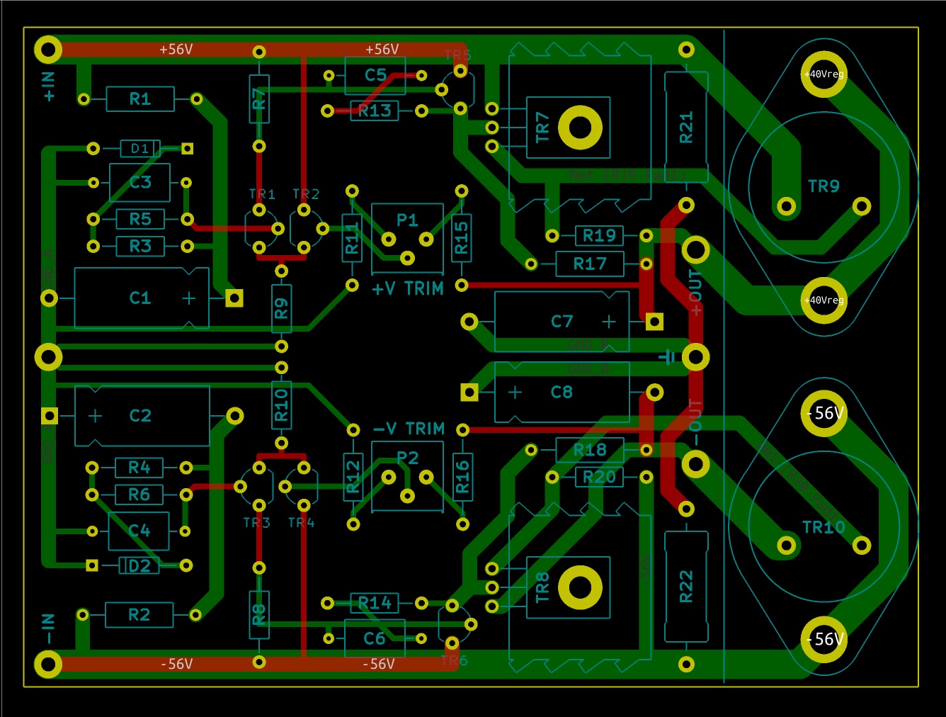
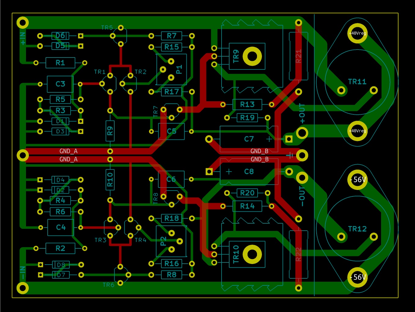
i finish my new clone of the NAP 250 i share my Kicad Files.
i finish my new clone of the NAP 250 i share my Kicad Files.
Good job!!!https://www.diyaudio.com/community/threads/naim-nap-250-original-clone-build-thread.390504/
i finish my new clone of the NAP 250 i share my Kicad Files.
And how you made preamp to this project ?
You use preamp ?
Good dayI search many times on the net, i never find the DR schematic. I just find the PCB of the 250. with schematics but as you saw there is mistakes on the PCB ... So it should be enterely verified on the original PCB by reverse engineering
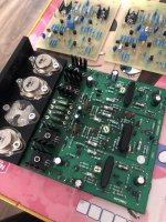
I buy the original NAP250.2 board
in this stage without one transistor
But nobody Known about NA00* Output transistors Volts/Ampers/h21e/max freq…
Good idea or not for DIY I don’t known
Richard D from Naim forum say only about 80 Ampers output current of nap250.2
Nap250.2 Monster transformer monster output currents for wat?
maybe Focal Utopia loads …Attachments
Last edited:
Dear JeffNaim NAP regulator (sans current protection):
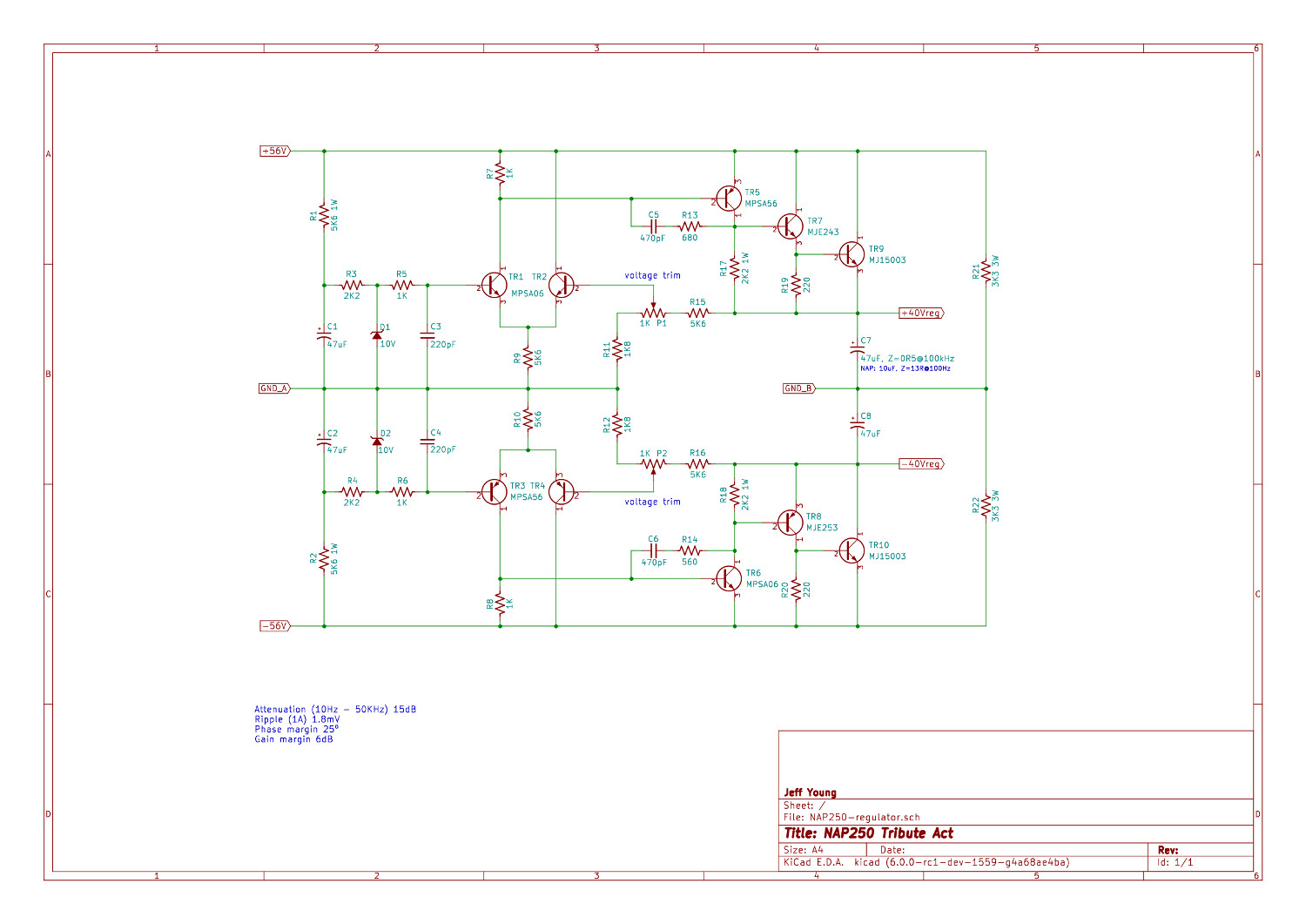
Modified regulator. LTP & VAS re-referenced to ground, CCS added for LTP, Miller compensation changed from local to global.
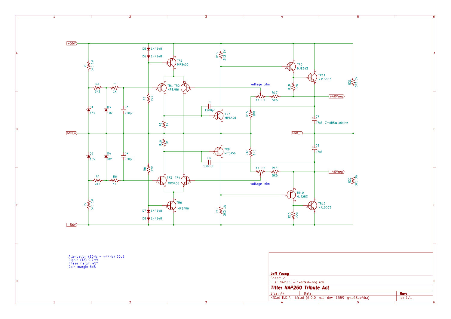
SPICE has the modified regulator giving vastly better performance in the higher frequencies:
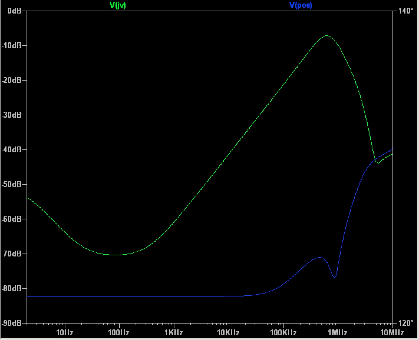
Can you hear the difference? Dunno. But I intend to find out.
Naim schematic board:
Modified schematic board:
its perfect work!!!
when I diy my 250 reg board i experiments with current sources in diff cascade and this issue have is more instability working with real amp board and loads.
p.s in new Naim design Steve S added the current source in every were … but sound is reality better with this ?…
Last edited:
- Home
- Amplifiers
- Solid State
- NAP250 clone