I bread-boarded this simple serial regulator for supplying G2 power. It is based on a 150V gas discharge valve but unloaded output is just a little above the expected 150V. That would be because of the unavoidable FET G-S voltage I presume. Is there a simple way to fine tune the output voltage for a couple of volts?Consider a VR tube to be like a zener. Good as a reference but not for high power.
You can however pass one with a FET and get a stable reference with more current capability. This becomes a voltage regulator.
Attachments

Last edited:
You can divide down the ref voltage before sending it to the gate. That will allow you to tailor the output to anything below the ref voltage.
But be aware that these ref voltages have a large spread, so for accuracy you may want to use a trimmer.
Then again, how accurate must that 150V be. Is 145V OK? 153?
Jan
But be aware that these ref voltages have a large spread, so for accuracy you may want to use a trimmer.
Then again, how accurate must that 150V be. Is 145V OK? 153?
Jan
Fabulous simple solution indeed, a resistor divider over the 150A1 -why did I not think of that 🙂 While pushing the E130L tetrode the G2 is known as its soft spot. Several people report valves were destroyed by too high G2 dissipation, keeping it safe at the recommended 150V is paramount.
In your vast experience, can you tell me this serial reg has the ability of sinking some current peaks? This article propagates the use of a shunt type. I wondered if an extra gas discharge tube per G2 would be beneficial for this purpose.
In your vast experience, can you tell me this serial reg has the ability of sinking some current peaks? This article propagates the use of a shunt type. I wondered if an extra gas discharge tube per G2 would be beneficial for this purpose.
Last edited:
As a series regulator it cannot sink current.
You can't just hang another ref tube on this output, as the output and the extra ref never are exactly the same value so either the ref is lower and the reg starts to dump current into the ref, or the ref is higher and doesn't do anything.
You'd need a shunt reg, but are you sure it is required?
BTW If you go for the dividing-down solution, make sure you account for the extra current that division part needs from the feeding current source.
Jan
Being in the 'gathering parts' stadium I do not know what to expect. It is a Ferrari with 27,5mA/V mutual conductance and suffering from secondary emission, being only a tetrode. Will see. Thank you again. https://frank.pocnet.net/sheets/009/e/E130L.pdf
I'm not a tube expert, sorry. No idea what this secondary emission can add up to, if anything.
Where's a tube guy when you need one ;-)
Jan
Where's a tube guy when you need one ;-)
Jan
With that circuit you don't need the tube at all.The CCS there gives a fix voltage over a resistor.I bread-boarded this simple serial regulator for supplying G2 power. It is based on a 150V gas discharge valve but unloaded output is just a little above the expected 150V. That would be because of the unavoidable FET G-S voltage I presume. Is there a simple way to fine tune the output voltage for a couple of volts?
You have have only to pick the right resistor for the wanted output.
Mona
Attachments
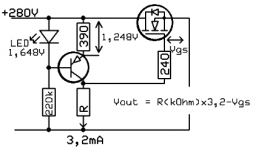
okee, that is speeding things up. 47K should give 145V .. so another 1K8 would be bulls eye. For the bonus of having an adjustable output, would running 3,2mA through a 2K multiturn trimmer (18mW) be acceptable? Adding a little resistance to the 390R will probably bring the collector current down a little. Am I still good at 1mA? Power supply sag will be no more than 12V at peaks, adding another 14V for mains fluctuation, still 130-26=104V remaining. Seems plenty.
Probably a silly idea but could a string of zeners at the regulator output take up the G2 surplus energy when the anode moves far below 150V? Zener noise would probably be an issue.
Probably a silly idea but could a string of zeners at the regulator output take up the G2 surplus energy when the anode moves far below 150V? Zener noise would probably be an issue.
Attachments

So what happens if the anode goes way below 150V? Does G2 then start to act as anode? But that still doesn't mean G2 starts to source current, does it?
Jan
Jan

With the 'dynatron effect' observed in tetrodes the G2 current is reversed because of secondary emission. With a penthode G3 returns the free electrons to the lower potential, at the expense of added capacitance.
Yeah but G2 doesn't source current, does it? That was the issue whether the G2 reg needed to shunt current.
Edit - just saw painted's post. Thanks.
Jan
Edit - just saw painted's post. Thanks.
Jan
Yes, absolutely. The specsheet mentions positive grid voltage on several occasions but I do not see a Class A2 loadline fit to the max dissipation limitIf the Va goes under 60V the Ig2 increases dramatically at max input swing (Vg1=0V).
Best to choose the loadline to stay above 60V at Vg1=0V.
Mona
 Edit - they probably mean the supply and not a positive grid voltage as such.
Attachments

Last edited:
- Home
- Amplifiers
- Tubes / Valves
- Need help trying to understand voltage regulators.