Having a while reading TL431 datasheet several times and could not find the proper answer. I guess it is beyond my knowledge now and would like to leave here the questions. Need your help.
1. In the datasheet there is a typical application schematics. The very first one should be simple shunt regulator schematic. The thing is there is always a resistor series between source and the shunt set. What is the purpose of this R? I would like to know how can we calculate this resistor value. The best clue I got is from some datasheets say to get 10mA min into TL431. Is this mean the minimum sink current?
I would guess that if I have 10v from source and I need 5v regulated. then I have to put 5 volts over this R. Does this mean I have to know the total current flow before I can get this R? What if the current is not constant?
2. What will be the output current to the load? Does this relate to the sink current? any limitations? any mistakes of my understanding?
3. If I have 5v and I need 5v out, can I remove this resistor?
4. On some implementation, there will be an LM317 or LT1085 configure as a CCS then the serial R then the TL431. How to calculate the Current required and the value of the serial R
So confuse now and hope someone could help.
Think of the total current into the load + the shunt as constant. The minimum for the 431 is usually 1mA. Using your example of Vin=10 and Vout=5. Take a class A discrete opamp consuming 20mA that varies it's current in each supply rail over the range of 10mA up or down. The 431 must pull at least 1mA when the opamp is drawing a maximum of 30mA the total becomes 31mA. Check the minimum opamp rail current @ 10mA, the 431 must now pull 21mA. We know that 31mA flows through the feed resistor, so it's R=161r, set to 160r. Check the power dissipation in the TL431 at maximum input voltage and at minimum load current and the dissipation in the resistor.Archwn said:1. In the datasheet there is a typical application schematics. The very first one should be simple shunt regulator schematic. The thing is there is always a resistor series between source and the shunt set. What is the purpose of this R? I would like to know how can we calculate this resistor value. The best clue I got is from some datasheets say to get 10mA min into TL431. Is this mean the minimum sink current?
I would guess that if I have 10v from source and I need 5v regulated. then I have to put 5 volts over this R. Does this mean I have to know the total current flow before I can get this R? What if the current is not constant?
You must be able to calculate the load current. The MAXIMUM VARIATION in the load current <=99mAArchwn said:
2. What will be the output current to the load? Does this relate to the sink current? any limitations?
It will not work. All regulators need to drop voltage to achieve regulation.Archwn said:
3. If I have 5v and I need 5v out, can I remove this resistor?
You don't need a CCS and a series R. But, the CCS probably has a resistor to measure it's output current. This resistor is part of the CCS. A 317 requires 1.25V across out to ref. It also needs between 1.3V and 2V (graph in datasheet) between in and out. The total voltage to operate 317 CCS is between 2.5V and 3.2V depending on output current.Archwn said:
4. On some implementation, there will be an LM317 or LT1085 configure as a CCS then the serial R then the TL431. How to calculate the Current required and the value of the serial R
First, go to datasheetarchive.com and download the motorola datasheet. Type in TL431 and scroll down near the bottom of the page to get the motorola sheet.
From the way you spoke it sounds like you are confusing a current reg with a voltage reg. The 431 keeps a constant current if used as a CCS (constant current source). It is actually a programmable zener.
Get the motorola datsheet and then post any problems that you have. We will then have common data.
Mark
shunt regulators
The big advantage of a shunt regulator is that the series resistor isolates the load from the main supply. With a larger difference between supply and shunt that resistor will have a larger value so isolation factor increases.
In some of our circuits (DAC and Phono preamp) we use an LM317/337 bringing the supply voltage down from 45 Volt to 30 Volt. Then a shunt regulator follows bringing the Voltage down to 18 - 24 Volt.
The TL431 is a nice thing but it has the disadvantage that at frequencies over 100 kHz the regulation is less effective. So it's a good thing always to have a capacitor there with good HF specifications. In our DAC we use an Os-Con 10 µF and a polyester 10 NF in parallel for the digital circuits.
When designing audio circuits, discrete or with op amps, a better option is to use a discrete shunt. Two transistors and a zener diode do the trick far better then the TL431.
In tube circuits a tube can be used for the shunt regulation.
Hi,
I breadboarded a 317 + 431 + BD140 (as PMA's schematic) a few days ago.
I scoped the DC and could not lock onto any frequency due to the low level of noise coming out of the assembly.
I estimate the wideband noise is about 0.3mVpp ~=100uVrms.
Not very low noise, but much better than many IC series regulators.
My next is adding a 20V Zener to the tail of the 431 to see if I can get +52Vdc out of the assembly (for a Krell Klone front end).
Archwn, I see now that you are building the shunt regulator. The R you asked about is to keep from burning out the 431. It is to restrict the current to within specifications.
Some of your source current will be used by the 431, some of it by the R1+R2 divider, and the remainder by your load.
If the load will not always be connected one must choose the resistor values so that the 431 will not get too much current with load disconnected. This is a disadvantage of the zener regulator, which is what this basically is.
The series pass regulator (fig 21 on motorola sheet) may be more practical. Unlike using a zener on the base of the transistor, the 431 puts feedback on the B-E junction such that the output voltage is not affected by the load.
The shunt regulator has the same load regulation, but the series pass configuration is not so delicate.
The really big advantage for the CCS + shunt regulator is, it is short circuit proof.
The CCS prevents serious damage downstream no matter how ham fisted one is.
It also happens to perform rather well.
The CCS prevents serious damage downstream no matter how ham fisted one is.
It also happens to perform rather well.
here is the CCS. Did you read the thread?Archwn said:
4. On some implementation, there will be an LM317 or LT1085 configure as a CCS then the serial R then the TL431.
AndrewT: Thanks for the reply.
I'm having a little trouble with the concept of a constant current-constant voltage power supply.
What is actually going on is that the CCS is a current limiter for a shunt regulator?
I'm having a little trouble with the concept of a constant current-constant voltage power supply.
What is actually going on is that the CCS is a current limiter for a shunt regulator?
My next is adding a 20V Zener to the tail of the 431 to see if I can get +52Vdc out of the assembly (for a Krell Klone front end).
Have you even seen zener noise on a scope? A zener must be near maximum current before it quiets down. Pass about 40% rated current through a zener and place the scope leads across it. A JAN zener is very quiet, gold doped.
The 431 is very quiet and also doesn't drift with changes in current.
Why not use a series of TL431s to raise the voltage?
Hi Hail,
why could I not think of that?
I reported the zener results here
http://www.diyaudio.com/forums/showthread.php?postid=1259146#post1259146
And yes, the noise has gone up by about 10db but the voltage has gone up by about 3db
why could I not think of that?
I reported the zener results here
http://www.diyaudio.com/forums/showthread.php?postid=1259146#post1259146
And yes, the noise has gone up by about 10db but the voltage has gone up by about 3db
Hi,
an update on the noise of the HV version of the 431.
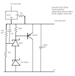
schematic posted here to save time.
The circuit as posted has 1.5mVpp noise (all at high or very high frequency, DMM meaures <0.1mVac)
Adding 100nF ceramic across the Zener reduces this to about 1mVpp.
However, The circuit as posted is feeding 30mA into 1k6.
When I add an extra 4k3 across the output, sinking 41mA and reducing the load on the shunting transistor, the noise drops again.
output , ...30mA, ......... 41mA
basic, ..... 0.3mVpp, ..................... LV operating @ 30V & 30mA
zener, .... 1.5mVpp, .... 1.0mVpp
+100nF, . 1.2mVpp, .... 0.6mVpp
Why does reducing the pass current in the shunting transistor reduce noise? And why so much?
It looks like I should investigate the optimum CCS current if output noise can be varied so readily.
BTW,
adding that 4k3//1k6 reduced the output voltage from 49.262V to 49.240 That's <0.05% for an 11mA increase in output current.
an update on the noise of the HV version of the 431.
schematic posted here to save time.
The circuit as posted has 1.5mVpp noise (all at high or very high frequency, DMM meaures <0.1mVac)
Adding 100nF ceramic across the Zener reduces this to about 1mVpp.
However, The circuit as posted is feeding 30mA into 1k6.
When I add an extra 4k3 across the output, sinking 41mA and reducing the load on the shunting transistor, the noise drops again.
output , ...30mA, ......... 41mA
basic, ..... 0.3mVpp, ..................... LV operating @ 30V & 30mA
zener, .... 1.5mVpp, .... 1.0mVpp
+100nF, . 1.2mVpp, .... 0.6mVpp
Why does reducing the pass current in the shunting transistor reduce noise? And why so much?
It looks like I should investigate the optimum CCS current if output noise can be varied so readily.
BTW,
adding that 4k3//1k6 reduced the output voltage from 49.262V to 49.240 That's <0.05% for an 11mA increase in output current.
Attachments
Andrew: I haven't looked closely at your results yet, so this assessment may be premature.
Possibly the noise reduction due to the extra shunt resistor is due to the fact that some of the noise is removed from the base of the BD140 and is thus not amplified. Or, a filter may be formed using junction capacitance.
Just in case you don't know, JAN means Joint Army Navy: milspec.
JAN zeners are extremely quiet. If you frequent surplus houses picking up JAN diodes is adviseable. They have a J, JX, JTX, or JTV in the part number. The milspec is M10950/159. There is often a code like CCCN or such. This is an obsolete manufacturing code for the military.
My question is will a stack of two 431s work properly? I searched the web for over an hour last night and found no ap-note or schematic that shows two of them.
The dynamic response of a 431 is much better than that of a zener, if I recall correctly.
Have you tried two 431s? My construction facilities are somewhat out of commission at the moment due to a huge mess so I can't test it right now. I have plans to start construction of some "brain children" hopefully in the near future.
This CCS + shunt regulator is a neat idea. Mark
Hi,
the cascaded 431s was put on test and works.
I am letting it cool again to take some more measurements.
First impression is that it is little, if at all, quieter than the 20V Zener without the noise quenching cap, but regulation seems improved (yes, better than <0.05%).
I'll get back, hopefully before I get ready to go out again this evening.
Two things stand out;
1,) it is cheap.
2,) it has a small footprint.
the cascaded 431s was put on test and works.
I am letting it cool again to take some more measurements.
First impression is that it is little, if at all, quieter than the 20V Zener without the noise quenching cap, but regulation seems improved (yes, better than <0.05%).
I'll get back, hopefully before I get ready to go out again this evening.
Thank PMA and many before him.This CCS + shunt regulator is a neat idea.
Two things stand out;
1,) it is cheap.
2,) it has a small footprint.
Next update,
the noise is down to about 1.2mV pp @ Vin=60V, Vout=49.666V Iout=30mA, and 0.5mVpp Iout=40mA.
Turning down Vin to 52.6V and everything is OK.
Adding that extra 4k3//1k6 holds output voltage steady <1mV variation.
Cold start-up voltage 49.672V
after 1minute Vout=49.668V
after 20minutes Vout=49.663V, yes just 9mV change over twenty minutes.
Now the surprise.
turning Vin down to 52.1V Vout still set to 49.666V and a 20MHz 1.2mVpp oscillation is evident. Do not know if this is in the CCS + Shunt or if it's an interaction between Lab supply and and the regulator.
Since a conventional PSU cannot simulate this Vin, I cannot easily check the cause.
As I turn Vin down further Vout drops in sync, since regulation has been lost and the 20MHz stays constant @ 1.2mVpp.
Next try 100nF across the lower 431.
noise is the same, no improvement, unlike the Zener +cap.
The Zener + cap is about 4 to 6db quieter than the second 431.
But the oscillation is now down to 0.9mV when Vin is too low to allow regulation.
Overall, quite a success.
I have all the bits from stock except a PCB. I wonder if stripboard performance is worse than a proper PCB with voltage tapping points and main current paths optimised?
The lower Zener was replaced with a fixed voltage 431, 1k2 lower leg and 15k to upper leg, then a further 1k2 to the upper 431 and finally the same 10k pot. so it's a string of four resistors from Vout to ground. I'll post a schematic tomorrow.
The 10k pot gives an output range of 36V to 57V, just enough to cover KSA50 & KSA100 Klones and dropping the 1k2s will allow The Leach clone to be supplied as well.
And rearranging the same components will work for a dual polarity supply with a common earth/0V/PSU common.
Thanks much for the comprehensive report.
Glad to know the stack of 431s work.
I will scrutinize your results later.
For now, do you use an oscilloscope? I noticed that you are using a DMM for measurements. If you are not using shielded leads the noise readings may not be reliable. Also, a DMM usually doesn't have much of a frequency response.
A good capacitor tutorial is on the General Atomics website. This is the best I have ever read. There are four different molecular mechanisms for dielectric action.
The specific point here is that the NPO ceramic has a different mechanism than a class II (X7R) ceramic. A small NPO, say 1000pf, may catch more of the noise. I'll check back later to see what you post, Mark
http://www.tnt-audio.com/clinica/regulators2_impedance2_e.html[/URL]
Here is an link about how the output impedance of the 431 is affected by a filter capacitor.
Here is an link about how the output impedance of the 431 is affected by a filter capacitor.
Re: Re: Need help understanding TL431
Hi Andrew and cheers mate. you really help me out indeed.
So it must be maximum possible current to load + 1mA to TL431 then?
If I check the minimum current to load is 200mA and the maximum is 298mA, which leave TL431 sink 1mA min to 98 mA max. (still in the operating limit?) is this still ok?
I didn't see drop out voltage in TL431 datasheet. So I assume that if I put low value for the serial R like 0.2R or 1R (to get very low voltage drop) will this work?
Now my understanding is that if the above mentioned total 31mA example is required, then we set the LMs CCS to be 31mA and the series R can be removed? as the current is now limited by the LM?
Cheers,
AK
Hi Andrew and cheers mate. you really help me out indeed.
AndrewT said:
Think of the total current into the load + the shunt as constant. The minimum for the 431 is usually 1mA. Using your example of Vin=10 and Vout=5. Take a class A discrete opamp consuming 20mA that varies it's current in each supply rail over the range of 10mA up or down. The 431 must pull at least 1mA when the opamp is drawing a maximum of 30mA the total becomes 31mA. Check the minimum opamp rail current @ 10mA, the 431 must now pull 21mA. We know that 31mA flows through the feed resistor, so it's R=161r, set to 160r. Check the power dissipation in the TL431 at maximum input voltage and at minimum load current and the dissipation in the resistor.
So it must be maximum possible current to load + 1mA to TL431 then?
AndrewT said:
You must be able to calculate the load current. The MAXIMUM VARIATION in the load current <=99mA
If I check the minimum current to load is 200mA and the maximum is 298mA, which leave TL431 sink 1mA min to 98 mA max. (still in the operating limit?) is this still ok?
AndrewT said:
It will not work. All regulators need to drop voltage to achieve regulation.
I didn't see drop out voltage in TL431 datasheet. So I assume that if I put low value for the serial R like 0.2R or 1R (to get very low voltage drop) will this work?
AndrewT said:
You don't need a CCS and a series R. But, the CCS probably has a resistor to measure it's output current. This resistor is part of the CCS. A 317 requires 1.25V across out to ref. It also needs between 1.3V and 2V (graph in datasheet) between in and out. The total voltage to operate 317 CCS is between 2.5V and 3.2V depending on output current.
Now my understanding is that if the above mentioned total 31mA example is required, then we set the LMs CCS to be 31mA and the series R can be removed? as the current is now limited by the LM?
Cheers,
AK
Hi,
Is the TL431 overloaded during any of these conditions?
I have 32mA +-8mA and I opted for the PMA version (which is mistakenly shown in the datasheet with an NPN pass transistor instead of PNP).
Vout=18V and Iout=30mA CCS=52mA, the BD140 gets quite warm. A To92 will overheat.
BUT, the R or CCS feeding current to the load + shunt MUST drop voltage. The lm317 I am using in CCS mode drops a minimum of between 2.2V and 3.1V over a fair range of CCS currents. The 317 runs from warm to hot depending on Vin.
I intend fitting a 20C/W to the lm317 and 14C/W to the bd140.
The dropping medium is required to drop a voltage from Vin to Vout.
The load pulls a nominal current.
The shunt pulls an extra current to ensure that Vdrop=Vin-Vout.
The CCS is an alternative to the R. It matters not that you are choosing alternative currents. The R is a cheap and easy way if the Vin does not vary much.
If Vin from typical mains transformers varies as much as usual with both loading and with mains voltage then the CCS works better provided Vdrop does not exceed the maximum that the 317 (or it's replacement) can withstand.
Now calculate the power dissipation in the 431 when (a) the load is drawing maximum current, (b) when the load is drawing nominal current, (c) when the load is drawing minimum current.If I check the minimum current to load is 200mA and the maximum is 298mA, which leave TL431 sink 1mA min to 98 mA max. (still in the operating limit?) is this still ok?
Is the TL431 overloaded during any of these conditions?
I have 32mA +-8mA and I opted for the PMA version (which is mistakenly shown in the datasheet with an NPN pass transistor instead of PNP).
Vout=18V and Iout=30mA CCS=52mA, the BD140 gets quite warm. A To92 will overheat.
A shunt regulator is NOT in series with the load. Therefore the 431 cannot have a Vdrop like a conventional series regulator. That explains why you can find no reference to Vdrop.I didn't see drop out voltage in TL431 datasheet. So I assume that if I put low value for the serial R like 0.2R or 1R (to get very low voltage drop) will this work?
BUT, the R or CCS feeding current to the load + shunt MUST drop voltage. The lm317 I am using in CCS mode drops a minimum of between 2.2V and 3.1V over a fair range of CCS currents. The 317 runs from warm to hot depending on Vin.
I intend fitting a 20C/W to the lm317 and 14C/W to the bd140.
no.then we set the LMs CCS to be 31mA and the series R can be removed? as the current is now limited by the LM
The dropping medium is required to drop a voltage from Vin to Vout.
The load pulls a nominal current.
The shunt pulls an extra current to ensure that Vdrop=Vin-Vout.
The CCS is an alternative to the R. It matters not that you are choosing alternative currents. The R is a cheap and easy way if the Vin does not vary much.
If Vin from typical mains transformers varies as much as usual with both loading and with mains voltage then the CCS works better provided Vdrop does not exceed the maximum that the 317 (or it's replacement) can withstand.
- Status
- Not open for further replies.
- Home
- Amplifiers
- Power Supplies
- Need help understanding TL431