Thanks.No problem with posting on the Vituixcad thread")
The KEF Blade 2 I guess is about 7" wide (just based on what's in the manual) and the XO is around 350Hz (although the baffle step would start around 1000Hz). https://www.shop.us.kef.com/pub/media/wysiwyg/documents/blade/Blade_Manual_ENG.pdfOk, the woofers could go on the sides instead. It's the position of the FR that sets where the baffle step is in this case.
Hence, if the cabinet is 8" wide and 16" deep then would the baffle step for the full range would be based on the 8" width and for the woofers would be based on where they are placed on the 16" baffle (they wouldn't be centered on the Y-axis)?There is bafflestep for both the wofers and the coax. In the blade-style, the BS of the woofers is higher than the XO (likely) and that tof the coax above.
The woofers shouls be essentially be omnidirectional (already in full 4π mode).
I thought push-push woofers wouldn't have any baffle step since the sound wave is going in both directions and wrapping around the speaker similar to what is described here but with a 90 deg. offset.
http://www.t-linespeakers.org/tech/bafflestep/intro-bds.html
https://www.diyaudio.com/community/threads/baffle-step-compensation-methods.230342/post-6908230
Directivity index in this case is how the response of the woofers stands up in the context of all angles.Thanks. I did not understand this "directivity index".
The Vituixcad thread is expecting you to measure your responses at all angles/directions. I'm concerned that you haven't made it clear what you expect from Vituixcad this time because I'm not sure that's what you're looking for.
Vituixcad might still be able to help you, but you may need to ask around for instructions.
Do you know what you are getting with this? You can measure impedance and look at TS parameters like fs and Vas. You can also do these things without buying anything so this doesn't add functionality, just convenience.Yes, I do plan to get a testing kit (see link) once I have selected the drivers.
You were asked about measuring responses at multiple angles with a microphone. You considered taking the factory response and combining it with a simulated box and baffle. This isn't bad but it won't be the same because the full range driver goes through cone modes which Vituixcad cannot be expected to simulate.
Yes. The height plays little role being so much larger.Hence, if the cabinet is 8" wide and 16" deep then would the baffle step for the full range would be based on the 8" width and for the woofers would be based on where they are placed on the 16" baffle (they wouldn't be centered on the Y-axis)?
I thought push-push woofers wouldn't have any baffle step since the sound wave is going in both directions and wrapping around the speaker similar to what is described here but with a 90 deg. offset.
Except for the bipole dip.
dave
Thanks Allen.The Vituixcad thread is expecting you to measure your responses at all angles/directions. I'm concerned that you haven't made it clear what you expect from Vituixcad this time because I'm not sure that's what you're looking for.
Vituixcad might still be able to help you, but you may need to ask around for instructions.
Do you know what you are getting with this? You can measure impedance and look at TS parameters like fs and Vas. You can also do these things without buying anything so this doesn't add functionality, just convenience.
You were asked about measuring responses at multiple angles with a microphone. You considered taking the factory response and combining it with a simulated box and baffle. This isn't bad but it won't be the same because the full range driver goes through cone modes which Vituixcad cannot be expected to simulate.
1. I was hoping to use VituixCAD to help me determine which woofer would work best with the MAOP7 if any at all. It might also be that there might be no decent affordable woofer that works.
2. You are right, the DATS system will not measure frequency response because it does not include a microphone. I don't build DIY speakers very often. The last pair was in 2012 (from Rick Craig's kit). I don't know if investing in an expensive B&K microphone and software like MLSSA or LEAp/LMS would justify the 1 or 2 loudspeakers I intend to build every decade or so.
3. I assumed from all the literature that the Mark Audio drivers have fewer of these cone nodes than other full-range drivers.
Best Regards and thanks for the guidance.
1. I was hoping to use VituixCAD to help me determine which woofer would work best with the MAOP7 if any at all. It might also be that there might be no decent affordable woofer that works.
They should be some 2-4 dB more sensitive, have quite extended HF response, reach as low as you’d like and go as low as you would like.
3. I assumed from all the literature that the Mark Audio drivers have fewer of these cone nodes than other full-range drivers.
The holy grail of FR is a cone that becomes smaller as the frequency goes up. Called the chaotic or TL region how well the designer mangages to achieve this also is a good indication of how well controlled the high frequency ringing is. The best MA do this very well. MAOP 7 is right near the pinnacle.
dave
I don't think there's much you can find out from Vituixcad to help you decide which driver to use that you can't already surmise. If anything, it might give you some information on the bigger picture of the design.
Fortunately choosing a woofer for a WAW should not be too difficult.
See that they are not so large that they beam at the baffle step frequency. Since you are using four, this is an easier choice. Don't worry too much about what the response looks like, you'll be crossing them anyway and besides, they're on the sides of the cabinet (I presume at this stage). Make sure the sensitivity is sufficient. Attend to your baffle shape/modes.
To be honest I think that the full Vituixcad method goes well outside of the common wisdom with regard to the Markaudio product. As it turns out there's not much to be gained from measuring the FR that way unless you wish to assess listening angles and to equalise based on power and to assess the magnitude of these modes. There certainly isn't a crossover up high.3. I assumed from all the literature that the Mark Audio drivers have fewer of these cone nodes than other full-range drivers.
Fortunately choosing a woofer for a WAW should not be too difficult.
The biggest issue is an embarassment of choices.
Let me ad dthis additional criteria: They are easily available where i live.
dave
Except for the bipole dip.
dave
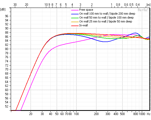
When you are referring to distance to the wall, is it the sidewall or the wall behind the speaker?
In my room, the left speaker is about 18" (450mm) from the sidewall and the right speaker does not have any sidewall. Both speakers are about 600mm from the wall behind them although there is a home theatre subwoofer behind my right speaker (I don't use the subwoofer for 2 channel music).
I assume, from your curves, that the bipole dip will be quite deep given the greater distance to the wall I have.
When you are referring to distance to the wall, is it the sidewall or the wall behind the speaker?
The sim can represent either a speaker on the wall with an “apparent” 2nd driver caused by the wall reflection or a bipole pulled out far into the room (ie ignores the room, and the seciond driver is real). The different curves represent the baffle width vrs the distance to the “2[su[]nd[/sup] driver (real or virtual).
ie, if you take your bipole, slice it vertically in half depth-wise and mount on the wall, you get the same response as the same bipole pulled far enuff out from the walls.
Below the dip one gets near perfect oomnidirectional radiation.
dave
So is VituixCAD not the right tool to use for designs involving Mark Audio drivers?To be honest I think that the full Vituixcad method goes well outside of the common wisdom with regard to the Markaudio product. As it turns out there's not much to be gained from measuring the FR that way unless you wish to assess listening angles and to equalise based on power and to assess the magnitude of these modes. There certainly isn't a crossover up high.
The biggest issue is an embarassment of choices.
I used loudspeakerdatabse and WINISD to filter out the woofers but am limited to what Madisound has in its portfolio. These were my parameters.
6" and or more
Xmax of 5mm
low sensitivity under 300hz (under 84db since I am using 4 of them)
are under $150 (since I need 8 of them)
and can work to in about 45L (F3 of under 50Hz).
The Morel drivers were all too sensitive, the ScanSpeak and Seas-Excel offerings were all over $200.
These are what I found
SEAS H1488-08 L16RNX - currently unavailable
SEAS H1480 L16RN-SL - QB3 alignment gives 110 liters or so but box volume can be reduced if port length is increased
SEAS H1869-08 L16RNX3 - expensive at $170 each (but they work well since the sensitivity below 300Hz is low)
SEAS H1878-08 L19RNX1 - same as above but even more expensive at $265 each
SEAS H1224-08 L18RNX/P - slightly too sensitive (as per the graph on loudspeakerdatabase it is close to 85db at 300Hz).
SEAS H1141-08 L15RLY/P - I haven't tried this in WINISD yet (its 5.5")
Let me turn the question around, are you trying to achieve more than other people already have?So is VituixCAD not the right tool to use for designs involving Mark Audio drivers?
There are two sides to crossover simulation here. One is the lower cross, which if it happens below the baffle step then it's easy enough to do using any crossover simulator or even by hand.
If it were me I would take polar measurements to learn how to EQ through the modes and decide where to listen. However that's only because I don't know the wisdom attached to using this driver.
Let me turn the question around, are you trying to achieve more than other people already have?
There are two sides to crossover simulation here. One is the lower cross, which if it happens below the baffle step then it's easy enough to do using any crossover simulator or even by hand.
If it were me I would take polar measurements to learn how to EQ through the modes and decide where to listen. However that's only because I don't know the wisdom attached to using this driver.
I don't know. I don't know what others have achieved with VituixCAD.
All I was trying to achieve was some level of sanity test and to determine driver matching (sensitivity, crossover, etc.).
I didn't get this. I am assuming this bipole is with one driver facing forward and another facing towards the wall behind the speaker. Is this correct? To simplify this let's take the worst curve (biggest dip) where the bipole is 200mm deep (On the wall, 100mm to the wall).The sim can represent either a speaker on the wall with an “apparent” 2nd driver caused by the wall reflection or a bipole pulled out far into the room (ie ignores the room, and the seciond driver is real). The different curves represent the baffle width vrs the distance to the “2[su[]nd[/sup] driver (real or virtual).
ie, if you take your bipole, slice it vertically in half depth-wise and mount on the wall, you get the same response as the same bipole pulled far enuff out from the walls.
Below the dip one gets near perfect oomnidirectional radiation.
dave
So if this bipole is pulled far into the room the response would have a dip? I assume this dip would be because the sound from the rear driver is hitting the wall and then reflecting and cancelling out with the sound from the front driver. Would the dip be related to how far the bipole was pulled into the room? I assume it would as the distance to the rear wall would define the time delay and hence the cancellation.
Can we simulate this in VituixCAD or any other software?
In the topology used by Audio Physic (Joachim Gerhard) and the KEF Blade, the woofers are on the side. Would these speakers experience the same dip even if the woofers are 90 deg off-axis?
FYI Joachim still employs this topology at Suesskind Audio.
https://suesskindaudio.de/wp-content/uploads/2020/05/HMJ-2019-01_Suesskind.pdf
I meant that the other way around. In any case...I don't know. I don't know what others have achieved with VituixCAD.
Simulating is good for finding your way around radiation and modal concerns. It's overkill if you want to know sensitivity, driver responses etc.All I was trying to achieve was some level of sanity test and to determine driver matching (sensitivity, crossover, etc.).
Last edited:
So if this bipole is pulled far into the room the response would have a dip?
Yes. The room complicates the situation, the graph is theoretical with no additional factors.
I assume this dip would be because the sound from the rear driver is hitting the wall
Forget the wall. In the bipole situation imagine an anechoic chamber. The sound flows around the enclosure to meet teh front. The dip is just below baffle step, and the drivers radiate omnidirectionally.
In the topology used by Audio Physic (Joachim Gerhard) and the KEF Blade, the woofers are on the side. Would these speakers experience the same dip even if the woofers are 90 deg off-axis?
If the woofer ar eequidistant from your ear there is no bipole dip, it is caused by yhr extra distance the sound from the back driver takes ti get around the cabinets. It is a pure geometrical construction (more or less)
Suesskind
I have only ever seen one dome woofer before.
dave
So I went through the instructions given by Member DciBeL in the link below.
https://www.diyaudio.com/community/threads/vituixcad.307910/post-7027808

MAOP 7 experts, How does one treat the dip around 3k and the peak around 10k? Especially that peak.

I tried everything including some very radical values for the crossover but was unable to tame those 2 aberrations.
Thanks.
https://www.diyaudio.com/community/threads/vituixcad.307910/post-7027808
MAOP 7 experts, How does one treat the dip around 3k and the peak around 10k? Especially that peak.
I tried everything including some very radical values for the crossover but was unable to tame those 2 aberrations.
Thanks.
Navin, that is on-axis, rarely do you listen to them on-axis.

True. I haven't heard the MAOP7 and am less worried about the dip around 3k than the huge broad peak centred around 10k even off axis. I tried the MAOP 7 with another woofer (SEAS Prestige L16RN-SL H1480) just to make sure I wasn't making some error.
FWIW, I owned a pair of MAOP7 for a couple years, I think it was, and in a couple of different enclosures never perceived anything approaching those graphs. To echo Allen’s query, when you say “tried”, does mean real world auditions, measurements, or simulations?
- Home
- Loudspeakers
- Full Range
- New Markaudio Drivers