I don't know what to say other than mine sounds fantastic.
1) You are using the most linear transistors you can buy
2) Jfets at input, give extremely low noise
3) Positive current feedback to improve damping factor
4) 2nd harmonic dominant. Phase doesn't even matter that much. Generg prefers positive over negative. The F4 is positive phase 2nd harmonic and people love it. Going negative phase is just for cloning purposes it's not the most important feature.
5) No capacitors in signal path
6) Low parts count
7) Class A Bias
8) Zero degeneration on output
Of course it's going to sound fantastic it's a bloody awesome amp no matter which phase you have. Just read that list of positive attributes again.
Also go read the F4 thread no one is complaining about having positive phase harmonic there. They bloody love that amp. I love it too.
The thing with this amp, in order to clone, it's going to be super sensitive to the transistor parts you have.
There is no such thing as a clone schematic it has to be designed around the operating points of the parts you have, which will be a little different for everyone one.
If you love the amp, the phase you have is completely inconsequential.
Last edited:
All good points - I agree. Since I built mine with a pot for variable positive feedback, today I went through the exercise of setting the DF with a 400 Hz test tone using some old Optimus LX5's. I measured the RMS output, alternating between disconnected speakers and connected. I settled on a DF of 150 on both channels with about 10 feet of 14 gauge speaker connected to each channel. This seems to be a sweet spot.
Of course, these speakers are pretty lame in the low end, so the next step will be to try it with my Martin Logans. I pity the poor amp 😀
Of course, these speakers are pretty lame in the low end, so the next step will be to try it with my Martin Logans. I pity the poor amp 😀
Awesome
Cool experiment.
I did the same types of experiments (as discussed earlier).
Cool experiment.
I did the same types of experiments (as discussed earlier).
Last edited:


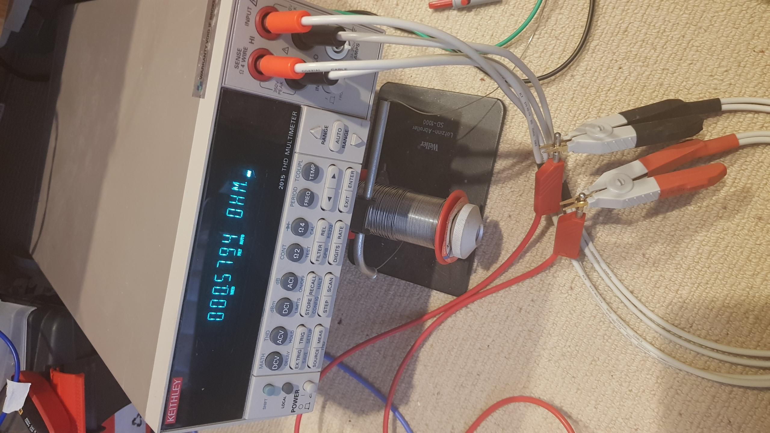
Nice - wish I had a low ohm meter with kelvins like that. 😀 Cheapest used 2015 on ebay is US$800. New $6000!!! 😱
Last edited:

Transconductance vs Frequency - P Chan Mosfet
Bias is 1A
Vds, 22V, 15V, 6V
No shelving on IXTH52P10P
Still more to come
Bias is 1A
Vds, 22V, 15V, 6V
No shelving on IXTH52P10P
Still more to come
Attachments

Last edited:
Purchased test leads - 579.4 mOhms
DIY test leads - 4.3 mOhms
DIY IS KING.
Hahahaha
Ha! That Keithley meter looks awesome! I think I have it's great grand Daddy in an old rack mount style, can't recall the model, but with LEDs, think it measures to 5 decimals, crazy accurate, well, crazy resolution, maybe not accurate 🙄 Too funny I just saw it yesterday when I was digging out my HP 339A.
Cheers
Last edited:
Mine is crazy accurate, at least tested against reference resistors.
It's kind of like a class A amp, you have to let it reach thermal equilibrium before it gets crazy good.
Hahahaha
If you use it when its cold there is about a 1% drift which is probably good enough most of the time.
It's kind of like a class A amp, you have to let it reach thermal equilibrium before it gets crazy good.
Hahahaha
If you use it when its cold there is about a 1% drift which is probably good enough most of the time.
I don't think my ears would hear 1% drift...haha 😀
My Tek 575 curve tracer has the opposite problem, it works perfect for 15 minutes but when it warms up, it starts acting up, horizontal trace jumps all over....gotta love ccts that use 10M R's in critical places, so many opportunities for them to F up.
So many projects...so little time...
Cheers
PS every time I get an email telling me new reply "Head full of Zombies....." I get the Men at Work song stuck in my head for a day....it's all your fault....
Last edited:
But the good thing about this thread...it keeps me plodding along as I have other things I am working on, farm, family, work etc. but getting a daily reminder there's audioactivity out there..it's great.
Cheers
Cheers


Hockey Puck IXTN40P50P
Hockey puck results might interest some people.
At some point I might create a new thread and summarise all of this, but I wanted to be happy with my test setup/methodology etc first.
Discovering I had some crap test leads earlier has probably affected the earlier results, the comparative ranking will obviously be the same etc so qualitatively still meaningful, but I will go back and retest everything.
Attachments

- Home
- Amplifiers
- Pass Labs
- On A Hippie Trail, Head Full Of Zombie