Ralph-
What is the AC voltage you getting at the output of the xfmrs? If you are running a 12VDC supply, the most you can be supplying to the secondaries of the xfmr is ~4.25VRMS, unless the amps are BTL, then double that reading (8.5VRMS). A 12V xfmr will have a turns ratio of ~8:1 so that would make the output voltage ~34VRMS or 68VRMS?
If you are using 12V xfmrs, you should be supplying ~15VRMS to the secondary which will require 48VDC rails for single ended or 24VDC rails for a BTL amp.
Hi there,
The transformers I am using are 0~12, 0~12 x 230 30VA toroidal
The first time around, using a 12V 20A supply I was using the primaries in parallel, so had 12:230V, being fed by a PBTL amplifier. With an amplifier output of around 6.5Vrms I was getting about 110V at the secondary of the transformer, but with some significant losses across the 1 ohm ballast resistors
I've revamped the setup as follows,
Now using a 24V 5A supply, with a 12v regulator to feed the 3 phase generator.
The transformer primaries are now in series so 24:230V, no longer need ballast resistors, but I've left 0.5 ohm resistors in to avoid a totally inductive load.
I've modified the input attenuator/lpf to allow a maximum amplifier output of around 15Vrms.
I've added 3x0.022uF 250Vac caps across each transformer secondary phase to eliminate any residual hf getting to the motor.
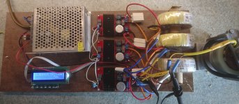
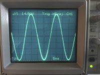
Here's a couple of pictures of the current setup, the first is the lashup version, soon to go into a suitable enclosure, and the second is the neutral - phase output, showing a clean, pretty accurate sine wave, with no HF noise.
I do think this is the most cost effective way of driving a multiphase motor, whether two or three phase.
Please post any questions, I'll try to answer as best I can.
The transformers I am using are 0~12, 0~12 x 230 30VA toroidal
The first time around, using a 12V 20A supply I was using the primaries in parallel, so had 12:230V, being fed by a PBTL amplifier. With an amplifier output of around 6.5Vrms I was getting about 110V at the secondary of the transformer, but with some significant losses across the 1 ohm ballast resistors
I've revamped the setup as follows,
Now using a 24V 5A supply, with a 12v regulator to feed the 3 phase generator.
The transformer primaries are now in series so 24:230V, no longer need ballast resistors, but I've left 0.5 ohm resistors in to avoid a totally inductive load.
I've modified the input attenuator/lpf to allow a maximum amplifier output of around 15Vrms.
I've added 3x0.022uF 250Vac caps across each transformer secondary phase to eliminate any residual hf getting to the motor.
Here's a couple of pictures of the current setup, the first is the lashup version, soon to go into a suitable enclosure, and the second is the neutral - phase output, showing a clean, pretty accurate sine wave, with no HF noise.
I do think this is the most cost effective way of driving a multiphase motor, whether two or three phase.
Please post any questions, I'll try to answer as best I can.
Attachments
Definitely putting this on the project list!
Does it make sense, and it does to me, to relax the 120V AND 50/60Hz motor restrictions? We can now control phase and amplitude and frequency the signal. Why not look into the Hurst/Papst/Premotec catalog for a better motor? The original motors were chosen with those major restrictions, we are not.")
Does it make sense, and it does to me, to relax the 120V AND 50/60Hz motor restrictions? We can now control phase and amplitude and frequency the signal. Why not look into the Hurst/Papst/Premotec catalog for a better motor? The original motors were chosen with those major restrictions, we are not.
Hi there,
The transformers I am using are 0~12, 0~12 x 230 30VA toroidal
The first time around, using a 12V 20A supply I was using the primaries in parallel, so had 12:230V, being fed by a PBTL amplifier. With an amplifier output of around 6.5Vrms I was getting about 110V at the secondary of the transformer, but with some significant losses across the 1 ohm ballast resistors
I've revamped the setup as follows,
Now using a 24V 5A supply, with a 12v regulator to feed the 3 phase generator.
The transformer primaries are now in series so 24:230V, no longer need ballast resistors, but I've left 0.5 ohm resistors in to avoid a totally inductive load.
I've modified the input attenuator/lpf to allow a maximum amplifier output of around 15Vrms.
I've added 3x0.022uF 250Vac caps across each transformer secondary phase to eliminate any residual hf getting to the motor.
Here's a couple of pictures of the current setup, the first is the lashup version, soon to go into a suitable enclosure, and the second is the neutral - phase output, showing a clean, pretty accurate sine wave, with no HF noise.
I do think this is the most cost effective way of driving a multiphase motor, whether two or three phase.
Please post any questions, I'll try to answer as best I can.
I see 3 resistors and 2 caps at each amp inputs. What these are for? Attenuator as V-divider with some caps as filters or Low Pass filters?
Hi Ralph
So on the first version the 12-230 trans where stepping up the 6.5 volts to 110 volts. That seems to go along with what pyramid calculated. He thought you where using a 12 to 120 step up. But with a 12-230 step up and the amps you are using the numbers seem to work.
With your new version what is the voltage after step up. With the 24-230 it would seem to be a lot lower. I must be missing something somewhere. Sure seems like a good idea to get rid of some heat wasting resistors.
Thanks Tom
To answer the above questions,
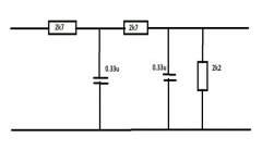
The input attenuator/lpf between the generator and the amp is now as below.
With the supply voltage for the amps increased to 24V I could reduce. the attenuation to allow a larger output swing without clipping.
I have left 0.5 ohm resistors between the amp and transformer as I found that just occasionally, if I had the output of the generator set near the maximum, the amps could still lock out.
It was suggested above that a timed relay could be used to short-circuit the resistors once the motor had started, I do have some small 4 pole c/o relays and might try this, though I find that running the motor at about 75~80V provides more than enough torque.
Attachments
Hi Ralph,
I did not notice this before, but your Amps have only one supply voltage instead of having a +/- supply voltage, making the max output voltage much lower.
The Sine Wave you displayed with a 24 Volt supply has a pk-pk amplitude of 14.9 Volt, which is only 5.2 Volt rms.
So you can never achieve 15 Volt rms (which is 42,4 Volt pk-pk) with one Amp having a 24 Volt supply.
When using the 12 Volt supply, you could only produce halve or some 2.6 Volt rms.
This resulted in at least 3.8 Amp rms in your 1 Ohm resistors.
Now I understand why the got hot.
Using a 24 Volt Trafo now for 5.2 Volt rms input means that the power transfer of trafo drops from 30Watt to (5.2/24) x 30 Watt = 6,5 Watt.
This may be just enough for your application but is probably saturating at start up.
That's why you still need 0.5 Ohm serie resistors.
More optimal would be to pick a trafo that better fits your needs.
Hans
Hi Hans,
Sorry, but the information you gleaned from my pictures wasn't quite correct.
I'll go over it point by point:-
First, you are correct that my amps are single supply, but I can achieve 15.65V rms using a 24V supply, before visible distortion occurs.
The amps drive power in both directions, not relative to ground "PBTL".
At this point the voltage at the motor is 109.5V rms, more than enough; I don't think I shall need more than around 80V.
What you saw in the picture as 14.9V was actually 149Vp~p ( x10 probe on scope), and was taken from the neutral tap to one of the phases, giving a phase~neutral output of 52.68Vrms, this corresponds to a line voltage of 91.24V.
If you look at the photo of the setup you will see that the output set to '50', there is no visible distortion at 60
As far as the need for the resistor to avoid saturation, I suspect you are right, but the addition of a timed relay to switch out the resistor should fix this.
Last edited:
Hi Hans,
It does seem too good to be true, but the proof is in the doing.
The most expensive part of the whole show is going to be a decent case
I reckon I can get the whole thing done for less than £100
I do think that when I box the unit up I might put in a couple of spare amps, just in case they're not obtainable in a few years time.
regards
Ralph
Hi Ralph
It is great what you and Hans have done for this thread. Not a lot of talk with with no completion like so many threads. We have two completed units using 2 different angles and they are working.
Ralph if I understand this, you put the output of signal of the amp on a scope and adjusted the input signal voltage to get a amp output signal just before clipping. Real world measurements gave you 15.65vrms amp output and 109.5 vrms at the motor after the .5 ohm resistors.
From the 1st version to the 2nd you increased the amp input from 12 to 24 volts.(I am assuming that is like raising the B+ on a vacuum tube. I know very little about transistor amps). So now we have a higher signal and then you halved the set up tranformers to get to 109.5 after the .5 resistors.
The voltage divider is used to lower the input signal so if you wanted a 100 volts at the motor would you do it here. Also maybe a pot here so you could adjust for each motor for least vibration. Also on the frequency gen it said 1-5 volt output so is the divider necessary???
Thanks Tom
Hi Tom,
You've pretty much got it all correct. The only slight correction relates to the divider; a little experimenting gave me an effective reduction of 5:1 with the 24V supply, the capacitors were added to create a low pass filter, in my case with a cut-off frequency of around 200Hz in order to reduce any HF 'hash' from the generator, the values are somewhat arbitrary, anything from 0.047uF to 0.5uF should do fine.
It is important that the resistor values are accurate, I use 2% resistors to ensure the voltages of the three phases are as close as possible.
Any adjustment of the output can then be done using the generator.
I will be very interested to hear how you get on with your setup when the parts all arrive. Keep us informed, and if there are any other questions please ask.
I'm on the lookout for a suitable case, and in the meantime producing a pulley for my motor, non standard diameter shaft
Ralph
Hi Tom,
Yes, I do have a fairly well equipped workshop, including 2 lathes, milling machine, bandsaw, drill presses, etc.
The problem I have is making something that will look good enough; I'm pretty good at making things work, not quite as good at making them pretty, especially in sheet metal.
Any suggestions would be gratefully received, but maybe should be done as a PM as this is getting a bit off of the original thread.
Thanks
Ralph
And here is a picture showing my gear.
From left to right:
Wall supply for the Project generator + Phase splitter.
The Quad 303, the trafo cabinet and the VPI motor driven by a 6 wire cable with Neutrik connectors, 4 for the two phases and 2 for the Quad 303 on/off switch.

Hans
From left to right:
Wall supply for the Project generator + Phase splitter.
The Quad 303, the trafo cabinet and the VPI motor driven by a 6 wire cable with Neutrik connectors, 4 for the two phases and 2 for the Quad 303 on/off switch.
Hans
Hi Hans,
I like your setup, can you post a few details of the transformers you are using?
Are you using your setup 'live' yet?, if so do you detect any significant differences?; ideally measured, but subjective will do
The Papst motor has much less vibration than the Thorens E50 original , but the isolation is pretty good and I fear that I won't notice any difference.
regards
Ralph
Hi Ralph,Hi Hans,
I like your setup, can you post a few details of the transformers you are using?
Are you using your setup 'live' yet?, if so do you detect any significant differences?; ideally measured, but subjective will do
The Papst motor has much less vibration than the Thorens E50 original , but the isolation is pretty good and I fear that I won't notice any difference.
regards
Ralph
My setup is already live and working trouble free for some 10 years.
The reason I constructed this, was because when putting the needle of the cart on an LP with the belt removed, but the motor running, I could clearly hear Rumble.
The research that I started resulted in this setup, where I heard no rumble at all.
See posting #25 for the measurements I did recently to show that even while playing an LP, in this case thus with the belt driving the platter, no signs of Rumble are visible in the spectrum, other than the "rumble" coming from the LP.
Since it is so long ago that I made this, I can't remember the details of the toroids, other than that they are 15V/230V and at least 30Watt each.
There are no stickers on them to do some detailed searching.
Hans
Last edited:
Hi Hans
Been playing with the two high torque hurst motors I have while waiting for my parts. These noisy monsters on in sperate 6" pods with lead all over the place. I wondered how much noise was getting to cart so tried your cart on the record no belt trick. Holy crap not a pretty sound!!!
I decided to get rid of this transfer of noise so I used some 29 cent rubber/cork/rubber pads and Baltic birch plywood. I isolated the motor pod/turntable/tonearm problem solved. Using the cartridge and amps for noise detection is a great idea.
When I was playing around I hooked up a fluke a/c meter to the amp speaker terminals. When the refrigerator kicked on the reading on the meter when up a lot. So I pulled the cart up meter when back to normal reading. So with the cart on the record it was picking up vibration from a refrigerator 20 ft away thru the wood floor up a rack with at least 500 lbs of stuff lead loaded MDF brass cones aluminium/wood plinif 32 lb lead loaded platter 1/4 PVC mat. So much for mass taking care of the problem. 29 cent rubber cork pads who would of thought??
Can not wait to get the parts to build the controller. Will let you guys know how it turns out.
Enjoy the ride
Tom
- Home
- Source & Line
- Analogue Source
- Optimally driving a (VPI) synchronous turntable motor