Is it possible that paralleling IC´s (or transistors) might bring up some issues that the designer need to consider as "tradeoffs" ?
I guess that paralelling two jfets is good for lowering noise but as there are no 2 identical jfets (and the connections between them always differ in lenght and shape) They might not work exactly at the same time, introducing distortions....")
I guess that paralelling two jfets is good for lowering noise but as there are no 2 identical jfets (and the connections between them always differ in lenght and shape) They might not work exactly at the same time, introducing distortions....
I found no problems to parallel OPAmps and the current drive ability goes up too. Off cause current noise goes up so it may not work as well for MM. Paralleling Fets rises the input capacitance and can lead to oszilation. That can be stopped with small value inductors. Some do not like the sound of ferite in the signal path though. I do not belong to those. A ferite bead here and there ( also in the PSU ) can do miracles. Diffenrences in the Fets can be trimmed out to a large degree. Distortion as well as offset. They can be preselected for Idss and Vgs if you are a perfectionist.
I found no problems to parallel OPAmps and the current drive ability goes up too. Off cause current noise goes up so it may not work as well for MM. Paralleling Fets rises the input capacitance and can lead to oszilation. That can be stopped with small value inductors. Some do not like the sound of ferite in the signal path though. I do not belong to those. A ferite bead here and there ( also in the PSU ) can do miracles. Diffenrences in the Fets can be trimmed out to a large degree. Distortion as well as offset. They can be preselected for Idss and Vgs if you are a perfectionist.
As syn08 showed and agreeing with my comments, matching JFET's for paralleling is unnecessary and an SMT inductor every group of two or four keeps them stable. I guess doing the exercise in Jan's magazine is in order. A Monte Carlo on a completely random selection of JFET's shows virtually no difference in noise.
CMRR @DC (dB) 135
PSRR @DC (dB) 140
Input IBIAS (nA) 180
Unity Gain BW (MHz) 55
Slew Rate (V/µs) 30
in (pA/√Hz) 3.75
MAX9632.pdf
Pretty gross Inoise.
As syn08 showed and agreeing with my comments, matching JFET's for paralleling is unnecessary and an SMT inductor every group of two or four keeps them stable. I guess doing the exercise in Jan's magazine is in order. A Monte Carlo on a completely random selection of JFET's shows virtually no difference in noise.
Yes, total Ygfs is what counts for gain and noise. Still, can they current hog if with enough IDSS differences and small/zero individual Rs?
Yes, total Ygfs is what counts for gain and noise. Still, can they current hog if with enough IDSS differences and small/zero individual Rs?
Not in a real practical application (i.e. the same color code). If you forced the issue and mixed violet 2SK170's with the lowest Idss grade there MIGHT be an issue but I still doubt it. The noise going as the fourth root of Idss is a real leveler.
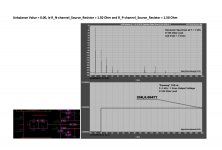
Sigurd Ruschkovski made a distortion analysis for me in a parallel symmetric input stage with N and P-Channel Fets. For example a 2SJ74BL has a Gm of 22mS at 8mA and a 2SK170BL has 20mS at 8mA so the P-Channel is a bit steeper. We put a trimmer inbetween to ground but adjusting it did not change much the distortion unless grossly off.
I will try to find the simulation.
I will try to find the simulation.
I guess their individual internal resistance in the tens of Ohm keeps them sharing current well?
No actually, it would be better that I presented the issue carefully so everyone could understand.
Here it is :
That meant a different transconductance total between P & N branches?
With a differential input, we have jfet matching problems, because serious mismatch will overload the servo, if too far off. Everyone here should also understand that jfets tend to turn off when run harder, so thermal runaway is not a problem, and this also forces a better match. Most here would hide any added distortion from mismatching inside a feedback loop and make it less obvious, but for the rest of us, it is critical.
Unfortunately, the ORIGINAL design that I hoped to concentrate on, seems long lost in the 'scuffle'. It IS a 40 year old design and it could be updated to be quieter and better, at least for audio, than it was originally designed. I had hoped to discuss a simplified transconductance amp or TA, version that would be a nearly ideal first stage, with or without global feedback, but we are pretty far off track.
Unfortunately, the ORIGINAL design that I hoped to concentrate on, seems long lost in the 'scuffle'. It IS a 40 year old design and it could be updated to be quieter and better, at least for audio, than it was originally designed. I had hoped to discuss a simplified transconductance amp or TA, version that would be a nearly ideal first stage, with or without global feedback, but we are pretty far off track.
Most here would hide any added distortion from mismatching inside a feedback loop and make it less obvious ...
You've actually polled everyone here to verify this as fact? Does making such a statement somehow elevate your ego?
No, negative feedback will generally suppress any nonlinearities on the input stage, I would presume. So, if you make a design that does not require exact matching, then there is no chance of distortion cancellation by the devices themselves, so it usually requires negative feedback to lower the inherent distortion generated to an 'acceptable' level.
Joachim and Salas, I have been working on this very problem for the last week, off and on. I, too, have a problem with jfet Gm differences, and differential matching. I make both kinds of designs, both single ended and differential, but the problems remain. I found that a tapped potentiometer giving a slightly different source resistance to the N devices compared to the P devices can be very effective in reducing distortion for single sided designs. For complementary differential designs, it is not clear if it gives enough advantage to be worthwhile. Knocked my servos out, though, through too much offset.
Does making such a statement somehow elevate your ego?
Does making such a statement somehow elevate your ego?
Please stay technical if you have anything technical to bring to the table. The community thanks you.
Hello Joachim, I have two questions to that (sorry, do not have much time right now, and not seing the specific circuit):so the P-Channel is a bit steeper .... some 10% more.
1. What if you mismatch the drain resistors (I/V) by the same amount as the transconductance mismatch, so that both halves have the same output voltage? would that not cancel out some of the distortion?
2. Using for instance a level shifter of opposite polarity, that has the similar but opposite mismatch in transconductance, would that not also cancel out distortion?
Does making such a statement somehow elevate your ego?
Please stay technical if you have anything technical to bring to the table. The community thanks you.
Not at all. I was merely pointing out yet another group jab disguised as something technical that the moderators continue to let slide, yet you set an example with the SAME question as I did as when criticizing my question.
It was EXACTLY my point that technical disagreements can be had without these continuous back door jabs intertwined with almost every technical point. I am not looking to attack anyone. But I get really tired of the constant undertone of the "us vs. them" mentality that spurs accusations of sub par intellect to others that don't follow in lock step to the same opinion, rather than providing factual or technical support for that opinion.
Pooge, unfortunately it is an 'us vs them' mentality, here.
I try to covey MY design approach, and I get attacked or berated by others for it. For example, I tend to not like to use large amounts of negative feedback, and the subsequent low open loop bandwidth associated with it. It has been my experience that it is less successful, than designing the most linear circuitry possible, and then making it as close to open loop both in increased open loop bandwidth and the least amount of global negative feedback that will meet specs for the product.
Often, others, in order to simplify circuit design and matching requirements, will add a lot of global negative feedback in order to 'bury' the intrinsic open loop distortion. This is another approach, and I do not personally think it is the best approach to audio design. However, if other designers want to promote this approach to audio design, they are free to do so, but it does confuse the situation when either the thread title has JC-3 or Blowtorch in it, because these designs are developed with my design approach in mind, rather than some others on this website.
- Status
- This old topic is closed. If you want to reopen this topic, contact a moderator using the "Report Post" button.
- Home
- Source & Line
- Analogue Source
- Parasound JC3 Phono