I forget which issue of AX I showed how to do that.
Didn't see that, but I meant with two complete 100% shields with one driven to eliminate capacitance. I was just fiddling with my Keithley electrometer which can get fairly "high" frequency response with 10^15 Ohm circuits. This type of cable is not that common and I never saw tone arm wire like this (not that I've looked). I would bet the Keithley low noise (mechanical) triax properly driven would be the best IC ever. The low noise is from a special dielectric formulated to minimize mechanical noise.
Didn't see that, but I meant with two complete 100% shields with one driven to eliminate capacitance. I was just fiddling with my Keithley electrometer which can get fairly "high" frequency response with 10^15 Ohm circuits. This type of cable is not that common and I never saw tone arm wire like this (not that I've looked). I would bet the Keithley low noise (mechanical) triax properly driven would be the best IC ever. The low noise is from a special dielectric formulated to minimize mechanical noise.
Yes, I did my entire preamp with driven shields. I included how to build the cables in the article. The only chatter I have seen about anyone else following up on it was some folks in Russia.
Driven shields have been done, before. Please remember that a cap load is NECESSARY with a moving magnet cartridge and most moving coils have an impedance of about 10 ohms.
This way you set the cap load at the preamp exactly where you want it.
Tried to make it into a Riaa.. using mr Joachim Gerhards bipolar/mosfet second stage...but the current output is hard to tame... .. using at split Riaa with the upper pole passive between stages and the other in the feedback of the second stage...I can get fairly close, but it is not very robust for tolerances and just small value changes sends it way off....Is there a trick there...??
Yes MiiB. I whould use a resistor to ground after the input stage and also a cap tp ground.
The formular is R x C = 75usec. R is the resistor to ground with the output impedance in parallel. In my design it was a resistor in series and then a cap to ground, second stage inverting. With this stage you need to make the second stage with a high impedance input and the 318usec and 3180usec active in the feedback loop.
The formular is R x C = 75usec. R is the resistor to ground with the output impedance in parallel. In my design it was a resistor in series and then a cap to ground, second stage inverting. With this stage you need to make the second stage with a high impedance input and the 318usec and 3180usec active in the feedback loop.
Joachim.. This was already how I did it...!! need to play a little more the the values...funny circuit as you adjust the gain and band-with with the GND resistor...Don't you also use the Neumann 4th time constant 3.18µs..??
Attachments
Last edited:
Yes, that is a transimpedance circuit. You have to transfer the ouput current into a voltage. The lower you make the resistor, the lower you make the gain and distortion and the higher you make the bandwidth to a certain degree. Is is kind of similiar to current feedback. I usually do not implement the Neumann constant but that can be done if you insert a small value resistor in series with the cap to ground. That coud be done switchable.
Hi Miib
There are a couple of problems with your circuit in post 309:
In the first stage, R9 and R10 should be about the same value as R1. With the values you showed, there will be little or no current through Q1 and Q2.
The second stage needs DC bias at it's input and also a DC feedback path.
I think you also have the inverting and non-inverting inputs of the second stage swapped around.
Cheers - Godfrey
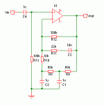
Perhaps a feedback network something like this could be used. There are probably a couple more caps than some would prefer, but none over 1uF, so decent film caps can be used without cost and physical size getting ridiculous.
The nice thing about a second-order system like this is that it allows decent low frequency response with reasonable values of R and C. It also allows quite a sharp cutoff at low frequencies which could be handy for a phono preamp, to deal with VLF from record warp.
The values shown are almost correct (but probably need slight tweaking). As is, the sim output looks to be about -0.5dB @ 20Hz, -7dB @ 10Hz.
The DC path for inverting and non-inverting inputs are also about the same, and not too high, for minimum DC offset in case a BJT input stage is used.
Attachments
Hi Joachim
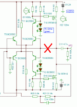
That looks nice. Do you use a trimmer in the second stage somewhere for DC offset? btw, Looks like a slight error in the drawing - see below. Hehe, I like that, it shows you know what the circuit's going to do without running the sim.
p.s. Sorry for cross-post
That looks nice. Do you use a trimmer in the second stage somewhere for DC offset? btw, Looks like a slight error in the drawing - see below. Hehe, I like that, it shows you know what the circuit's going to do without running the sim.
p.s. Sorry for cross-post
Attachments
Oops, maybe. I was originally considering this scheme (minus the eq) for a power amp, so wasn't concerned about noise at the time.Don´t you think that this 10kOhm to ground could be kind of noisy ?
edit: If the first stage has a gain of 40dB before eq then in the bass and mid that 10K is only equivalent to a 1ohm noise source at the input to the first stage. However it will be the dominant noise source in the upper treble. I'm not sure how bad it will be though.
edit2: It causes about 6uV RMS noise at the output, by my calcs. Should be acceptable?
Last edited:
Oops too ! Good you found the short circuit. Yes, my circuit should be trimmed by adjusting the source resistors. The Fets very much go astrey in terms of Vgs especially when you use them with lower idle current. The Vgs - Ids curve is very bend in that region.I build the inverted circuit that MiiB was showing ( without his mistakes i hope ) without trimming and the offset was ca.3V. Yes, i do not simulate much. There are several other people here that do that faster and better then me. Where i am good at is finding topologies that are maybe not that common.
Joachim, in the first stage of your circuit, wouldn't it be better to replace C1 and C9 with a single capacitor across R20? That would save one component and give better power supply rejection in the treble (although that's probably not needed).
The second stage you and Miib are using reminds me of Nelson's F5 amp. Your feedback network looks like it has low enough impedance to be used in a "current feedback" scheme like the F5. i.e. connect the feedback directly to the emitters/sources of the input devices instead of using long-tailed pairs. Do you think that would be possible? It would allow for some simplification.
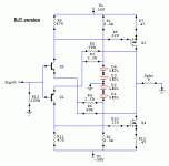
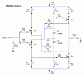
OT, but maybe of interest: here's a couple of variations on the F5 topology to allow for different kinds of input device. The Mosfet version only got invented because swordfishy was designing an amp and wanted to use ZVN3310As and ZVP3310As for the input as he already had some and didn't have easy assess to decent Jfets. The BJT version originally had a different output stage so resistor values are probably all wrong, but hopefully you get the idea.
I hope he won't be mad at us, but it's all in the spirit of developing a decent, affordable phono preamp, which I think was his intention a couple of days ago.Sorry John, i hope this is not a kind of thread jacking.
Attachments
- Status
- This old topic is closed. If you want to reopen this topic, contact a moderator using the "Report Post" button.
- Home
- Source & Line
- Analogue Source
- Parasound JC3 Phono


