THD+N
The Phase Linear 400II has just been converted to full comp 🙂 (just have to add speaker protection board, not a lot of room in the 400 II) and I'm going to convert another one later this year. It was not to hard to do w drawings but their was a lot of steps to do on the board and removing a bunch of parts and a lot of rewiring on the back plane (and add all new PNP and NPN output transistors) , soldering, added 2-wires, moving wires and double checking everything. Next one will be easier. Will be adding the WO control board as the last update.
The 700II in the drawing resistor installed R105/R204 , 220k installed from RCA input to ground? both my 700 II don't have it installed. Should it be installed?
This is Stephen Mantz from Zed Audio.
I have read the posts on this thread with great interest.
Here are my comments.
The Phase Linear designs are crude at best. Bob Carver is a very clever guy but his knowledge of amplifier design makes me wonder.
I have been working on PL amps since 1974 when the first 700 arrived.
Crude design, no degeneration on the diff pairs, no base stoppers in drivers, no constant current for the diff and VAS stages.
When these amps were designed, complementary devices were available and they were used extensively in SAE and of course GAS amps. James Bongiorno knew full well the dangers of quasi outputs so he used comp devices in series to have larger SOA.
The pro amps I built in South Africa in the late 60s and 70s were all series type complentary designs and at that time I had never heard of James or his designs, but I recogonized the dangers of quasi designs.
Look at the SOA curve of any decent output tranny and then do a spreadsheet with them in series. You will see that less devices are required than parallel. Yes you need twice the amount of drivers.
Think of the few pennies it would have cost to add a CC to the diff pair instead of the various R-C dropper circuits he used in different revisions. Same with the VAS. A pair of resistors and a bootstrap capacitor cost just pennies less than a constant current.
The PL909 and the variants are totally unsuitable for these amps. The SOA plot of 5up/5 doen on a split 100v rail is so bad.
Someone posted that the SOA of the 2119 ir better than the 024s. I disagree as I have data sheets up and at 70v Vce they can both pull just over 3 amps at 25C. At 30v Vce they can both pull 8 amps! Someone needs to check their data sheets a little more carefully.
Does anybody think of the typical phase angle of a large woofer. It is typically close to 60 degrees and this will cause twice the heat dissipation as compared to a pure resistive load.
Does anybody look at the impedance curve of typical speakers versus frequency...I guess not.
So in my humble opinion, taking the PL designs from the 700 to the duall 500 and the 400 is a waste of time.
Quasi output stages CANNOT compare to a full complementary design..period. The top and bottom devices do not operate in the same conditions. The top is an emiiter follower and the bottom devices are common emitter. They are unstable at best especially with triples.
It is impossible to bias these for low THD at 20KHz without a big puff of smoke.
Look at the PL compensation networks. No Miller feedback to tame the VAS instead their is a VAS to ground shunt capacitor and then a feedback cap from the VAS to the return diff base. Then there are the ferrite beads on the output devices' bases to tame further oscillation.
The White Oak boards look nice but if you put lipstick on a pig it is still a pig.
When PL went to that LF351 front end they made the problem worse as the amp could not support the massive open loop gain and have stability.
I will not even mention the lack of any DC protection in these amps. Seen too many speakers take a trip to Valhalla.
My PL upgrades are simple. Remove the guts of the PL, increase capacitance as much as physial size permits and I put my own drive board in...fully complementary, all the usual CC circuits, DC protection, input AC mains surge protection {check the line current surge when hitting a 20,000mfd with 85v DC or in case of PL700 with 33,000mfd at 100v DC Not a pretty sight] and I add in signal sensing on PL400s as they have no on/off switch.
My latest is a the removal of the TO3 sockets and I now have a mother board with all the high current output stages, DC protect, signal sense, turn on surge protect.
The drive boards plug onto the mother.
I use Toshiba 2SC5200/2SA1943 as my drivers with smaller TO126 as the first stage of triple.
Full series output stage so in a PL400 I have an output stage of 2+2 in series on top and 2+2 in series on the bottom. These devices now work from a +/- 42v rail and so their SOA is massive and 4 ohm reactive loads are driven with ease.
PL700 is similar but now I have 3+3 on top and 3+3 on the bottom and the devices work off +/-50v. Check the SOA curves at these lower Vce numbers and you will see what I mean.
My driver stage uses split Miller compensation..that's it and the amp is stable.
Oh I forgot, the thermistor does not carry mains any longer, it simple shuts off the speaker relays.
Unlike the PL designs, my driver transistors all run in pure class A and I am able to bias the amps to about 2 watts in pureclass A into an 8 ohm load though the sinks ti run warm like this.
I 100% remove the rail fuses.
Regards

The boards with the LF351 front end can be made stable by adjusting the Miller and lead compensation values to the right ones. The values Bob Carver used were dead wrong. Miller comp needs to be 47 pF and lead comp from VAS output to op-amp inverting input 27 pF. You could also take a lesson from darn near the same topology in the CS800 and apply some local feedback from the output to the emitter of the MPSA93 (set for gain of about 60), and use an MJE350 CCS instead of that silly bootstrap drive. Even a quasi output is stable with MJ15024’s, but if you are going to all that trouble you may as well re do it full comp because it just plain sounds better. These mods can easily be done with the original or replacement boards.
The MJ15024 does have “enough” SOA for the PL400 with 4 ohm load but not at 2. The 2119x is a little better above 80 volts, but not enough to write home about. Unfortunately there is no output device on the market with enough SOA for the 700. The voltage is just too high without going to series-parallel or class H. The 15024 does well enough for domestic use but it’s still a gamble.
The MJ15024 does have “enough” SOA for the PL400 with 4 ohm load but not at 2. The 2119x is a little better above 80 volts, but not enough to write home about. Unfortunately there is no output device on the market with enough SOA for the 700. The voltage is just too high without going to series-parallel or class H. The 15024 does well enough for domestic use but it’s still a gamble.
Why would anyone want to use a front end with an opamp? Open loop gain is not the issue, rather intelligent design is.
One issue which plagues bipolar devices is secondary breakdown and if one looks at SOA graphs you will see that putting transistors in series keeps them away from the Isb limited area. The PL700s I redo are safe into 2 ohm loads as the outputs are running at an effective +/-50v and having 3 up and 3 down allows for a more reliable amplifier, all other things in the front end being done correctly.
One issue which plagues bipolar devices is secondary breakdown and if one looks at SOA graphs you will see that putting transistors in series keeps them away from the Isb limited area. The PL700s I redo are safe into 2 ohm loads as the outputs are running at an effective +/-50v and having 3 up and 3 down allows for a more reliable amplifier, all other things in the front end being done correctly.
Using the MJ21195G and MJ21196G it has Better SOA, here is the print of the op ampThe boards with the LF351 front end can be made stable by adjusting the Miller and lead compensation values to the right ones. The values Bob Carver used were dead wrong. Miller comp needs to be 47 pF and lead comp from VAS output to op-amp inverting input 27 pF. You could also take a lesson from darn near the same topology in the CS800 and apply some local feedback from the output to the emitter of the MPSA93 (set for gain of about 60), and use an MJE350 CCS instead of that silly bootstrap drive. Even a quasi output is stable with MJ15024’s, but if you are going to all that trouble you may as well re do it full comp because it just plain sounds better. These mods can easily be done with the original or replacement boards.
The MJ15024 does have “enough” SOA for the PL400 with 4 ohm load but not at 2. The 2119x is a little better above 80 volts, but not enough to write home about. Unfortunately there is no output device on the market with enough SOA for the 700. The voltage is just too high without going to series-parallel or class H. The 15024 does well enough for domestic use but it’s still a gamble.
Attachments

"Ed said this
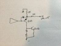
700 series II fully comp amp PL-36 pc boards. This involves removing the 120pF cap (C106/C206) that is in series with the 12K ohm resistor (R128/R129) next to Q106/Q206 and installing a 56pF cap in parallel with the 12K ohm resistor. This will greatly reduce the classic crossover notch and THD levels (particularly at lower volume levels) that you see with many Phase Linear amps (at 1kHz, 1 watt, 8 ohms). In which case the bias should be adjusted to approximately 385mV (which also works better when the 10 ohm resistors are nearer the nominal value of 10 ohms)."
After reading this I edit the drawing and Don't know what he meant do you think this correct?????
Attachments

A lot of this is way over my head lol.This is Stephen Mantz from Zed Audio.
I have read the posts on this thread with great interest.
I will not even mention the lack of any DC protection in these amps. Seen too many speakers take a trip to Valhalla.
Oh I forgot, the thermistor does not carry mains any longer, it simple shuts off the speaker relays.
Regards
I have not had any problem w mine and I'm also using w computer fans.
But a speaker protection board are cheap to install,, but Less room in the 400 II, I want to install it inside, I have it external now.
I also thought about running the thermistor's to the speaker protection board and also thinking of removing the Ac outlet which would removes the 120Vac in that area (700 II). I don't like that the thermistors is about 170 degrees seems way to hot , Might change it to 140,150?
That’s what he meant. But the correct value for the cap is really 27 pF. 120 is WAAAAAAY too much. I still prefer to run that cap off the VAS instead of the output (ie, in the original position) and use a full comp output which lets you use ANY bias setting without oscillation, so you can decide for yourself how hot you want to run it. And putting a 10k from the output, and 150 ohms to ground on the emitter of that MPSA93 goes a loooooong way toward making it stable. Gets rid of the excessive open loop gain, and the local feedback does some of the distortion correction so overall distortion is no worse. And put a reverse protection diode on the base emitter of that tranny, too.After reading this I edit the drawing and Don't know what he meant do you think this correct?????
What is VAS? And I converted it to Full Comp 400II and one have a 700II is also Full comp and Using the MJ21195G and MJ21196GThat’s what he meant. But the correct value for the cap is really 27 pF. 120 is WAAAAAAY too much. I still prefer to run that cap off the VAS instead of the output (ie, in the original position) and use a full comp output which lets you use ANY bias setting without oscillation, so you can decide for yourself how hot you want to run it. And putting a 10k from the output, and 150 ohms to ground on the emitter of that MPSA93 goes a loooooong way toward making it stable. Gets rid of the excessive open loop gain, and the local feedback does some of the distortion correction so overall distortion is no worse. And put a reverse protection diode on the base emitter of that tranny, too.
VAS = the 40412. “Voltage amplifier stage”.
If you‘ve converted to full comp with 2119x (or 1502x in the 400) you solve 90% of whats wrong with them. The rest falls into the category of minor tweaking. Unless you re-build with a whole new design - which some do.
I‘ve converted one of my 400’s to full comp, and the other will eventually. I’ll probably buy a set of Cylon meters for it and turn it into an S2 look alike (it’s an original, and the faceplate is beat to heck and the meters don’t fit right anymore because of the previous owner’s bad rack mount conversion). I’ve considered building up a 700 S2 look alike running class H. I’ve got a pair of 40-0-40 trafos that would be perfect to power it, plenty of MJ21193/4, and heat sinks that will fit a chassis of that form factor.
ThanksThat’s what he meant. But the correct value for the cap is really 27 pF. 120 is WAAAAAAY too much. I still prefer to run that cap off the VAS instead of the output (ie, in the original position) and use a full comp output which lets you use ANY bias setting without oscillation, so you can decide for yourself how hot you want to run it. And putting a 10k from the output, and 150 ohms to ground on the emitter of that MPSA93 goes a loooooong way toward making it stable. Gets rid of the excessive open loop gain, and the local feedback does some of the distortion correction so overall distortion is no worse. And put a reverse protection diode on the base emitter of that tranny, too.
1. Ed said 56pf for c106 so what's the different between 56pf versus 27pf? and org 120pf?
2. also pleases check the drawing and the Op-amp that you suggested, is this correct?
will I do this this? I don't know its a big change, So what will this improve overall?
(I was during some testing w a SQ wave I'm getting some over shooting, more on the leading edge, would this change help remove this?
Note- w no output connected including the RC output network to Ground it has a Perfect SQ wave but when the Relay kicks in than I get the overshooting, Testing before and after the speaker protection board turns on )
3. (later when I'm done,,,, I'm going to add a thread w pics on how to convert from quad to Full, since I'm doing more than one , I want to make updated drawing and have good Pictures and than have a step by step temp plate, w less thinking on the next one But a lot having double checking)
4. what about adding just a blocking resistor?
Thanks Steve
Attachments

I run 27 pF for C106, but leave it in its original position. 56 pF may be the correct value in the new position. Almost anything smaller is an improvement over that 120 pF.
You have the added 10k resistor in the wrong place. It goes from the emitter of Q103 to the amplifier output. The idea is to provide local feedback around two gain stages inside the overall feedback. This is the way it’s done in the Crown and Peavey amps which use the same basic circuit - and why they are more stable. Also, the diode does not go in series with the base of Q103, it goes in inverse-parallel with the base-emitter. And you have it backwards which wont work at all.
You have the added 10k resistor in the wrong place. It goes from the emitter of Q103 to the amplifier output. The idea is to provide local feedback around two gain stages inside the overall feedback. This is the way it’s done in the Crown and Peavey amps which use the same basic circuit - and why they are more stable. Also, the diode does not go in series with the base of Q103, it goes in inverse-parallel with the base-emitter. And you have it backwards which wont work at all.
ThanksI run 27 pF for C106, but leave it in its original position. 56 pF may be the correct value in the new position. Almost anything smaller is an improvement over that 120 pF.
You have the added 10k resistor in the wrong place. It goes from the emitter of Q103 to the amplifier output. The idea is to provide local feedback around two gain stages inside the overall feedback. This is the way it’s done in the Crown and Peavey amps which use the same basic circuit - and why they are more stable. Also, the diode does not go in series with the base of Q103, it goes in inverse-parallel with the base-emitter. And you have it backwards which wont work at all.
Diode makes know sense to me? and its in Parallel w resistor?
Attachments


Both of mine are 400’s. One was originally an S2, and the other was converted. It was the original version, in bad shape. The driver board got replaced with a home brew S2 with a few mods (Including that one, and using a real current source instead of the boot strap drive). Thinking about buying a pair of the cylon LED meter boards for it too. The diode is just a 4148 - fast diode is needed, and since the op amp can only put out +/13V at 30 mA it doesn’t need to be beefy. Schottky would probably work as well.
The PL400/700 circuit tends to get more unstable the higher in voltage you run it. I’ve got a prototype PL700-S2 running class H (just a circuit board on a bench) that I want to one day build into a PL700 chassis, if I can find a completely dead one. Again, uses the PL 700-2 circuit with the local feedback added, smaller lead comp capacitor, and a current source in place of the boot strap. It will not work at all as a quasi-comp - uncontrollable oscillations when the rails switch. Dead quiet going full complementary. The same circuit running off just the low rail (+/-58V) is as stable as I’ve ever seen a PL - with any output transistor set. Run down at +/-28 volts and I have a hard time making it oscillate.
The PL400/700 circuit tends to get more unstable the higher in voltage you run it. I’ve got a prototype PL700-S2 running class H (just a circuit board on a bench) that I want to one day build into a PL700 chassis, if I can find a completely dead one. Again, uses the PL 700-2 circuit with the local feedback added, smaller lead comp capacitor, and a current source in place of the boot strap. It will not work at all as a quasi-comp - uncontrollable oscillations when the rails switch. Dead quiet going full complementary. The same circuit running off just the low rail (+/-58V) is as stable as I’ve ever seen a PL - with any output transistor set. Run down at +/-28 volts and I have a hard time making it oscillate.
Thanks You have a lot of knowledge. good to know, I might do it , at the moment I don't think I have any problems. (I have a glitch at high volume w less than 4 ohm speakers) but I'm Going to buy "Digilent Analog Discovery 2" that can do some Audio Testing, The software is growing in popular and has been updated their software. and theirs also some 3rd party software out their to. (Thanks TheStuffMade from youtube)Both of mine are 400’s. One was originally an S2, and the other was converted. It was the original version, in bad shape. The driver board got replaced with a home brew S2 with a few mods (Including that one, and using a real current source instead of the boot strap drive). Thinking about buying a pair of the cylon LED meter boards for it too. The diode is just a 4148 - fast diode is needed, and since the op amp can only put out +/13V at 30 mA it doesn’t need to be beefy. Schottky would probably work as well.
The PL400/700 circuit tends to get more unstable the higher in voltage you run it. I’ve got a prototype PL700-S2 running class H (just a circuit board on a bench) that I want to one day build into a PL700 chassis, if I can find a completely dead one. Again, uses the PL 700-2 circuit with the local feedback added, smaller lead comp capacitor, and a current source in place of the boot strap. It will not work at all as a quasi-comp - uncontrollable oscillations when the rails switch. Dead quiet going full complementary. The same circuit running off just the low rail (+/-58V) is as stable as I’ve ever seen a PL - with any output transistor set. Run down at +/-28 volts and I have a hard time making it oscillate.
Should all the Ceramic Capacitors be replace? (bad reviews about this type)
It appears that the Mica Capacitor are a lot better w less noise but cost more?
Since people are update to WOB boards they are selling them on E-bay but they are way to expenses , prices will I think come down has more are available , ED might be selling some to.
Note- Since I can't edit or update previous Posts I Updated Pics. and wrong ones
Attachments


Any cap used for frequency compensation in any position needs to be a class 1 ceramic, or better. These days, you may have problems finding C0G types in >100 volt. Even 15-20 years ago it was getting tough, so when I was stocking my lab and found 500 volt micas for a quarter, I loaded up on the values I use. Now I don’t have to resort to using 1 kV Z5U’s for Miller caps anymore. Since they drop capacitance rapidly with increasing voltage, they need to be run way the hell above rating to keep them linear. They are ok as bypass caps and snubbers. Leave them there on the vbe multiplier and on the protection circuit - they don’t hurt anything, the voltage on them is low and doesn’t change much with respect to the signal. Polystyrene caps are good (better than mica by a long ways - much lower loss) but they are even harder to find, expensive, and very fragile. I’m not sure I’d trust my “anti-oscillation caps” in an amp running off 200+ volts driving expensive speakers to them. One mechanical failure can be catastrophic. And I’ve seen the leads break off of the stupid things.
- Home
- Amplifiers
- Solid State
- Phase Linear 700b refurb and full complementary conversion