yeah that's the lacquer colour, not part of a deliberate design - however it was a little blood sweat and tears.....
The 6059 > 6CG7 > EL34 amp has been working great, doing 10-14 hours a day almost every day for nearly 4 months.

I finally managed to get a decent picture showing all of the grids with decent depth of field.

I finally managed to get a decent picture showing all of the grids with decent depth of field.
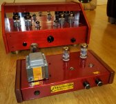
Bottlehead Seductor, uses EL84 tubes for about four watts.
And do I see a Quickie in there? Plus a Quicksand? Someone appears to be a Bottlehead fan! I have a Quickie I built plus a cathode follower version of the Quickie I built from scratch. I should post them.
Yes you see a Quicksand and Quickie, I also have a couple of SEX amps which I will post photos shortly.

Very nice work. I built a power amp with a blue top. Wood is nice and I see you also use Cat5 for hookup. I use it a lot.Bottlehead Seductor, uses EL84 tubes for about four watts.
Member
Joined 2009
Paid Member
The 6059 > 6CG7 > EL34 amp has been working great, doing 10-14 hours a day almost every day for nearly 4 months.
https://flic.kr/p/2k3Wt4W
I finally managed to get a decent picture showing all of the grids with decent depth of field.
https://flic.kr/p/2k3Wt2m
nice!
Bottlehead SEX 2.0 amplifier, uses two 6DN7 tubes, for 2 watts per and also functions as a headphone amplifier.
Checking out the Bottlehead website isn't allowed at work because of the SEX amp.
It triggers computer security to check if we've been accessing "inappropriate" websites. Got a visit from one of those characters accusing me of looking at porno at work. They didn't think it was funny when I showed them what the Bottlehead SEX amp was. No sense of humor at all.
Oh come on that -is- funny. Glad the university I work at doesn't even bother with that kind of nonsense, they would be kicking in doors all day long because plenty of our search terms would look suspicious to some dumb algorithm

My very early design 300b SE
Hi
posting pics of my very early design, first design Atwater breadboard type amplifier. Plenty of time so I made all calculations, schematics, all hardware, hanwinded the power and output transformer, also made a simple hand winder and so on. To much spare time I guess but I wanted to go deep and understand the whole design process from start to end.
Attachments


Member
Joined 2009
Paid Member
I made a RIAA preamp for a friend.
Separate power supply.
Separate power supply.
Attachments


Hi
posting pics of my very early design, first design Atwater breadboard type amplifier. Plenty of time so I made all calculations, schematics, all hardware, hanwinded the power and output transformer, also made a simple hand winder and so on. To much spare time I guess but I wanted to go deep and understand the whole design process from start to end.
So how did it work out?
Member
Joined 2009
Paid Member
I made a RIAA preamp for a friend.
Separate power supply.
Very nicely done.
I assume that's an Aluminium top painted black - do you have any challenges with good paint adhesion ?
Yes allu.
I use MOTIP primer and paint.
And a good,sanding (800) and degreasing with soap and nail brush. before paint.
The paint is dry within a day, so you can build the day after.
The blue LED under the EZ81 rectifier tube is not only for bling.
It is attached to the bleeder resistor,so no blue no voltage .
Also build in a timer mute relays on the out and a anti turn of thump circuit.
All the filter condensators are sorted out (<1%)
After a week ore two it sounded beyond expectations.
Last edited:
So how did it work out?
Thank you for asking!
Well, I thought it was splendid at first but have become more and more critical.
I have a steady hum probably from bad filtered B+. I use only a CLC filter 47u+5H+47u. Have learnt to ignore the hum somehow. I think it is lacking som highs, seems to roll off from 15-16k. Can't hear much over 13k anyway. It goes really deep, house shaking, type base but it definitely lacks punch compared to other amplifiers I'v built. To sum up, it hums, lacks highs and swampy bass but other than that... Maybe my schematic was too simple. Surely could need some good advice, haven't given up on the thing yet.
A new version of Hercules prototype, almost ready.
Class A1 push-pull amp, 45W per channel.
Unbalanced RCA and transformer balanced inputs, 0 dB.
4, 8, 16 0hm speaker outputs.
Continuous variable damping factor cоntrоl, from negative output resistance active servо-damping) tо positive (current drive). Almost inaudible soft saturation when overdriven.
Attachments

variable damping factor cоntrоl,
Superb. A variable transconductance tube amp.
:^)
dave
Superb. A variable transconductance tube amp.
:^)
dave
A bridge in feedback loops, with the current transformer.
Attachments
- Home
- Amplifiers
- Tubes / Valves
- Photo Gallery