Hi.
My name is Daniel and i am a new member in this forum.
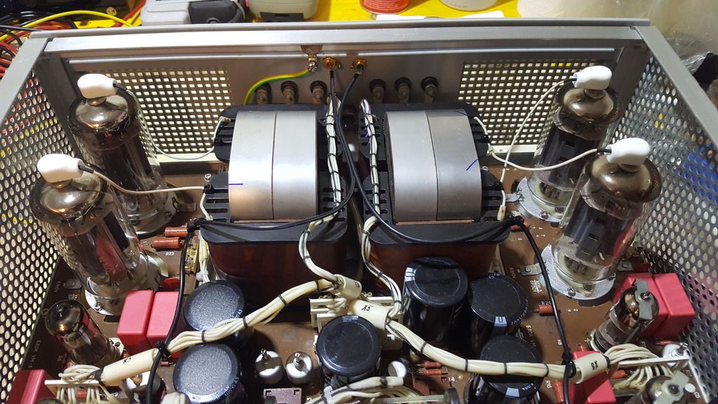
I have a Priboj amp which i rebuilt.
Currently it looks like this:
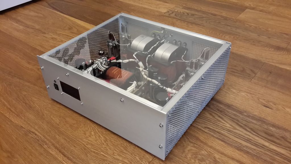
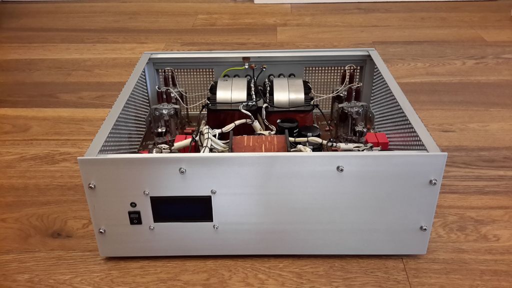
The display shows the anode current for all four tubes.
I swapped the 6P3C-1 tubes with GU-19 but i am not happy with the result...
Looking at the data of both tubes it looks like the impedance of the GU-19 is about 1/2 of the impedance of the 6P3C-1. I think this is the problem...
GU-19: https://frank.pocnet.net/sheets/018/g/GU19-1.pdf
6P3C-1: 6P3C-1, 6R3S-1
As the OPT of the Priboj has 2,7k ohm, which is pretty low, i thought that a 6P45S might work!? The russian equivalent for PL519.
I have 450V anode voltage in my amp. The G2 voltage is stabilized and adjustable so i can set a new value for the 6P45S easily.
What do you guys think, shall i give it a try?
Will it work with a 6P45S at the given Values of OPT and anode voltage?
This should give about a 100 Watts right?
Regards, Daniel
My name is Daniel and i am a new member in this forum.
I have a Priboj amp which i rebuilt.
Currently it looks like this:


The display shows the anode current for all four tubes.
I swapped the 6P3C-1 tubes with GU-19 but i am not happy with the result...
Looking at the data of both tubes it looks like the impedance of the GU-19 is about 1/2 of the impedance of the 6P3C-1. I think this is the problem...
GU-19: https://frank.pocnet.net/sheets/018/g/GU19-1.pdf
6P3C-1: 6P3C-1, 6R3S-1
As the OPT of the Priboj has 2,7k ohm, which is pretty low, i thought that a 6P45S might work!? The russian equivalent for PL519.
I have 450V anode voltage in my amp. The G2 voltage is stabilized and adjustable so i can set a new value for the 6P45S easily.
What do you guys think, shall i give it a try?
Will it work with a 6P45S at the given Values of OPT and anode voltage?
This should give about a 100 Watts right?
Regards, Daniel
Just guesstimating out of my head..
2k7 OPT means 675 ohm per tube on class B.
450V / 675 = 666 mA which mean Ipeak should be slight lower than that. Let's say 575mA.
Assuming the class B load line crosses saturation point at Vak 50v then your output power is:
Po=Vswing x Ipeak / 2 = (450-50) x 575mA / 2=115W. Considering OPT losses, i'd say you are correct about getting around 100W.
6P45S is a good choice for modified Priboi, much better than typically seen GU50.
In general, most Priboi modifications have much smaller output power than original.
I have built some p-p amplifiers with 6P45 and the performance is good.
With 2,7k OPT the expected output power is 100 W and above.
Optimum screen voltage for 6P45S is some 150...170 V and regulated.
Concerning the Priboi, the supply voltage of the 6N6P phase inverter should be increased up to some 400 V. So it must be derived from the supply of output tubes and essential amount of filtering should be added.
The GNFB (negative feedback) components must be re-dimensioned. If the total GNFB is below some 15 dB the stability of the whole amplifier is obviously better.
Originally the GNFB is above 20 dB.
And C10 (300pF) at the 6J32P must be removed.
Hi.
Thank you for the answers!
artosalo, thanks for the explanation. So i just have to supply R10 and R11 with 400V...?
Circuit: https://plus.google.com/photos/100591562823636348352/album/5441146835836083041/5441172140580553122
Thank you for the answers!
artosalo, thanks for the explanation. So i just have to supply R10 and R11 with 400V...?
Circuit: https://plus.google.com/photos/100591562823636348352/album/5441146835836083041/5441172140580553122
Yes. I think that at present the 230 V supply voltage is not optimal for a LTP phase inverter that should generate relatively high signal voltage with small distortion.
I used 410 V with 6N1P LTP.
I used 410 V with 6N1P LTP.
Attachments

Last edited:
Ok thanks!
artosalo i have some more questions - if you don´t mind.
What is the bias current for each 6P45S? don´t know if the power supply is strong enough...
Does the phase inverter work with 400V without any changes of the resistors R9 to R12?
Now the negative feedback has a 240p cap and a 6,8k resistor.
What values are needed for <15dB?
I saw that you have 47p and 27k - will it work for the priboj?
Regards, Daniel
I do not have my memos concerning this amplifier now on hand, but as far as I remember, the minimum THD was achieved with some 60 mA idle current. My output transformer was 2k, which differs from the value of Priboi.
I allways adjust the operating point of the output tubes with distortion analyzer.
I have to correct my earlier stories. Priboi obviously has a DC-connected cathodyne phase splitter, not a LTP.
I am quite sure that original Priboi circuit will work with 400 V supply.
If some adjustmet is required, the right place to make fine tuning is R9.
The DC voltage across the phase splitter tube should be some 200 V and 100 V across resistors R11 and R12.
This is not very critical since higher supply voltage improve the headroom of this circuit so much.
You have to measure the required value of R5. I can't tell you this, only estimate, which I don't like to do.
First you must measure the output voltage without R5 and C3. Use small input signal (1 kHz) that gives some 10...15 Vac output to 8 ohms resistive load.
Then connect some 50 k trimmer potentiometer in place of R5 and adjust it until the output voltage drops the amount you want. For example from 10 V to 2,0 V is 14 dB.
The value of C3 can be determined with 10 kHz square wave signal.
With GNFB connected the value of C3 is adjusted until the waveform is closest to original
Below two examples. The first would be ideal 10 kHz square wave, and the second quite typical with average class output transformers.
Attachments


Last edited:
Alright, thank you very much!
I just ordered the tubes + sockets - they are more expensive than i thought. Hopefully it will work well...
Regards
I just ordered the tubes + sockets - they are more expensive than i thought. Hopefully it will work well...
Regards
Expensive ? Where did you order ?
I found "new" tubes at 16 USD/pc. 6P45S EL509 6KG6 Audiophile Svetlana Tetrodes Lot of 2 | eBay
I do not recommend to buy from Ebay those that are sold as "used".
There is no sensible reason that used but completely OK tubes would be available.
Another cheaper alternative is 6P42S. It is same tube as 6P45S, but has different pin order.
http://www.ebay.com/itm/Vacuum-Tube-6P42S-6KG6-TETRODE-SVETLANA-NEW-/131941516586?hash=item1eb853c52a:g:dkYAAOSwJQdXDWNT
Last edited:
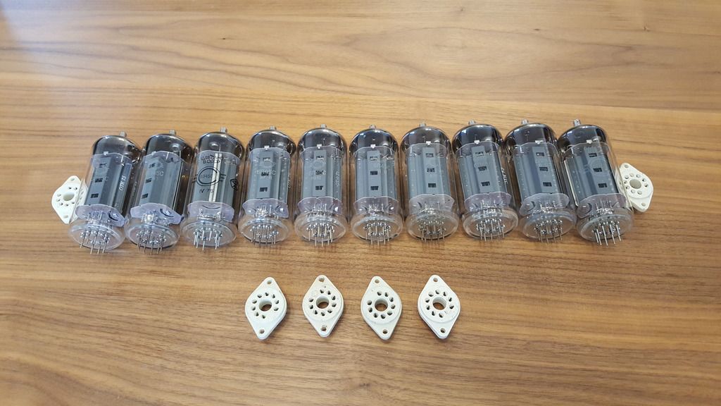
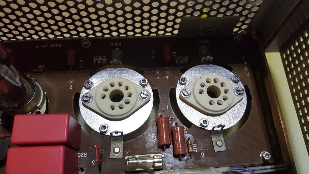
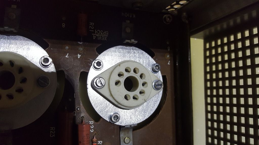
The tubes and sockets arrived today.
First thing i have to make is an adapter to fit the new sockets on the priboj PCB.
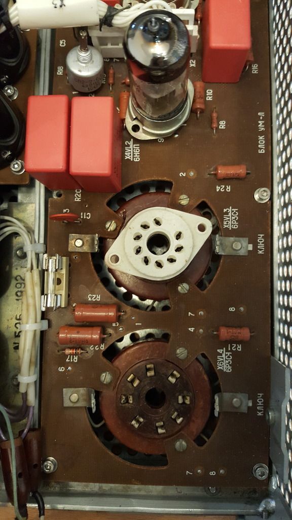
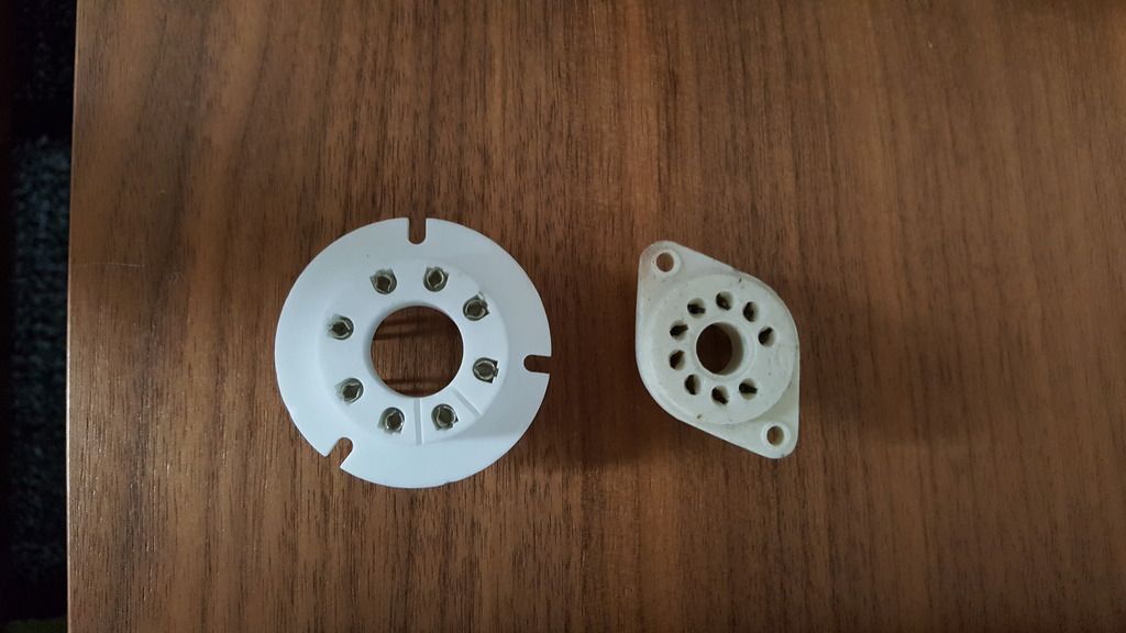
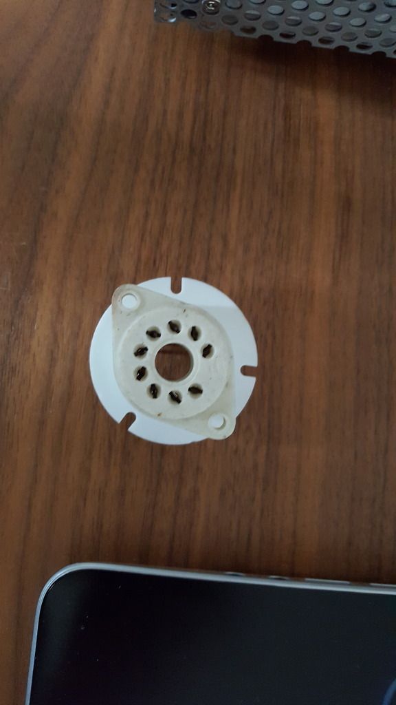
First thing i have to make is an adapter to fit the new sockets on the priboj PCB.


A little bit of progress 🙂
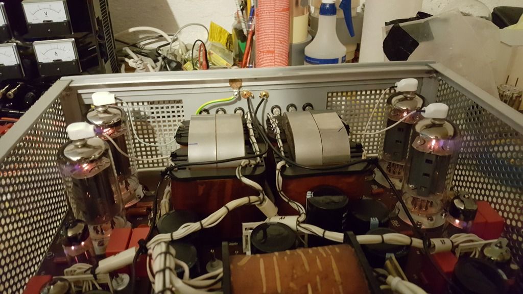
First thing i did is test the heaters. The original tubes have a 12,6V heater but the 6p45s needs 6,3V so i just connected them in series.
Two 6p45s in series need a bit more current than 2 parallel original tubes.
When i measured the voltage directly on the tube pins i got values between 5,7V and 6V. Is it enough??
That heater voltage is bit low, but should work fine.
Those 6P45S tubes look like they were originally designed to be in Priboi.
Well done !
Those 6P45S tubes look like they were originally designed to be in Priboi.
Well done !
I also had that thought... As there is enough space - i added one single turn on the transformer and connected it in series with the heater winding.That heater voltage is bit low, but should work fine.
Now i have values between 5,9V and 6,4V 😛
(after 1min of heating - need to take a look at after 20min or so)
Those 6P45S tubes look like they were originally designed to be in Priboi.
Well done !
Thanks!! 🙂
Yesterday i added another turn on the heater winding and i replaced one tube which had a "lower ohmic heater" with another one.
Now all tubes have 6,3V +-0,2V.
Today i built the adjustable and regulated G2 supply for the 6P45S.
I set the G2 value to 170V and also adjusted the bias current to 60mA per tube.
Just did the first test of the amp - it works.
Those tubes are really powerful... It did not take to long for the two 250mA slow blow fuses to blow ^^
They are located at the cathodes of the 6p45S tubes.
What value would be sufficient?
The pre stage of the 6P45S is still running on 240V.
I also did not remove C10 yet and i did not re-dimension the GNFB - but i will do that soon!
My Priboi schematic shows a common 0.4 A fuse for one channel (=two tubes).
Some 0.5...0.63A should be OK, if 0.4A fuses still blow.
But to blow 0.5A fuse reguires at least 100 W to take out of the amplifier.
It would be interesting to see the test results of a Priboi with 6P45S.
I think I am not the only person interested in.
Some 0.5...0.63A should be OK, if 0.4A fuses still blow.
But to blow 0.5A fuse reguires at least 100 W to take out of the amplifier.
It would be interesting to see the test results of a Priboi with 6P45S.
I think I am not the only person interested in.
Alright OK, thanks.
Of course i can do some measurements but at first i want to max out the full power of the amp. I have some big 3,9 Ohm 100W resistors - two of them in series should give a nice dummy load 🙂 oscilloscope and function generator are also available - so i can post some results when the amp is finished.
Yesterday i removed the C10 caps.
Next thing i want to do is increase the voltage supply of the phase splitter and then rework the negative feedback.
Right now the amp is more powerful than the original design but i think it is also far away from delivering 100W.
I am excited to see the results when the phase splitter is running on 400V.
Said and done.
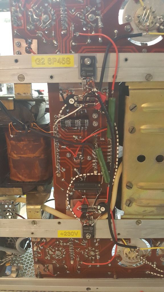
The two mosfets are part of the regulators for G2 voltage of the 6P45S and for 230V supply of the first stage. The big green resistors are 6,8k Ohm for the phase splitter supply. I had them at hand and used them - now i get about 385V on on R10 and R11.
This is not the final wiring, let's call it a "test setup" ^^
I think the output power has increased.
The bass is now really powerful but the heights are a bit distorted i think.
Tomorrow i will take a look at the feedback circuit and do a first power test with the dummy load.
Is it ok to test the power output at 1kHz?
Should i also use some different frequencies like 20Hz and 10kHz or so?
My plan is to ramp up the input signal until the output begins to clip - is that OK?
1 kHz is good test frequency to get a reference. Also all (or most) fine tuning should be done at 1 kHz.
After completed you can check the performance below 50 Hz and above 10 kHz ofcourse.
You can quickly check the clipping level, but don't keep that level more than a few seconds. Output tubes are overloaded easily and cathode currents are excessive.
After completed you can check the performance below 50 Hz and above 10 kHz ofcourse.
You can quickly check the clipping level, but don't keep that level more than a few seconds. Output tubes are overloaded easily and cathode currents are excessive.
artosalo, thank you very much for the support! 🙂
I have another question regarding the negative feedback.
There is a 240pF cap, C3, should i remove it, keep it or change it?
I will replace the 6,8k resistor R5 with a potentiometer to adjust the feedback.
I have another question regarding the negative feedback.
There is a 240pF cap, C3, should i remove it, keep it or change it?
I will replace the 6,8k resistor R5 with a potentiometer to adjust the feedback.
- Status
- Not open for further replies.
- Home
- Amplifiers
- Tubes / Valves
- Priboj with other tubes