Hi
I managed to brick the device. There is no bluetooth name after power.
I try to set name by HYT toolss (wouldnt change it) and QCC toll (Could not see the board).
So I try to set it via config app in BlueSuite, change the name and send it to board. Now I can not read the board, but I can see it. I have dump (.xuv) from NVS app and have keys saved in config app.
If I plug it in linux I see:
673310.030555] usb 3-3: New USB device found, idVendor=0a12, idProduct=4010, bcdDevice=16.69
[673310.030562] usb 3-3: New USB device strings: Mfr=0, Product=0, SerialNumber=0
Is there any hope to restore it?
Did you manage to communicate the module at the end?Hello
Do someone can help me with usb connection with qcc5125?
Drivers seems to work, I can see the qcc5125 in the ADK Configuration Tool and can configure it,
but I cannot connect to it in qcc tools to change name, nor in qact to configure DSP.
You will find screenshot of the differents involved windows.
Thanks a lot
Hugues
View attachment 1231058 View attachment 1231059 View attachment 1231060 View attachment 1231061 View attachment 1231062 View attachment 1231063
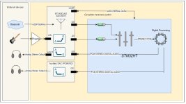
Hello guys, I am running a big project now and I am a bit lost with the bluetooth part. It seems like some of you have been playing with these modules so if i could get some general guidelines would be super helpful. I posted an image of the block diagram just in case.
Basically what I strictly need from the BT module is:
In addition, it would be nice to have:
I have been checking QCC3031 modules like the BTM331 or TS3031 which, on paper, seem to meet all those requirements.
However, I have no idea on how to procceed with the configuration of these modules. Things like routing analog inputs to I2S outputs, or configuring the firmware to send serial data over UART whithout stopping A2DP sink.
So to do these things, should I procceed just connecting over USB to the D+ and D- pins and configure all these peripherals with ADK? Or do I have to do it with SPI and CSR programmer? Any recommended development board which doesn't cost 800$? When using ADK/MDE can I brick the module? I don't even know what things you can change with ADK because I still couldn't connect a module to my PC.
So far what I did is, I bought some of these modules on aliexpress, some of them embedded on speaker amp boards which will be kind of my low-cost development board. While they arrive I downloaded MDE and ADK and have been reading the QCC3031 sink firmware, but it would be cool not to edit code on the firmware obviously.
Sorry if this was too long, thanks to all the folks who posted here their experiences with these. Any suggestion will be super appreciated.
I promise that I will share the proccess when I get some of these things done.
Basically what I strictly need from the BT module is:
- Receive AptX audio and stream it over one I2S interface.
- Simultaneously be able to receive some serial data and send it over UART/I2C/SPI etc.
In addition, it would be nice to have:
- Mic/line inputs routed to one I2S output just to act as a PCM ADC.
- The speaker diff output routed to play what comes from one I2S input just to act as a PCM DAC.
I have been checking QCC3031 modules like the BTM331 or TS3031 which, on paper, seem to meet all those requirements.
However, I have no idea on how to procceed with the configuration of these modules. Things like routing analog inputs to I2S outputs, or configuring the firmware to send serial data over UART whithout stopping A2DP sink.
So to do these things, should I procceed just connecting over USB to the D+ and D- pins and configure all these peripherals with ADK? Or do I have to do it with SPI and CSR programmer? Any recommended development board which doesn't cost 800$? When using ADK/MDE can I brick the module? I don't even know what things you can change with ADK because I still couldn't connect a module to my PC.
So far what I did is, I bought some of these modules on aliexpress, some of them embedded on speaker amp boards which will be kind of my low-cost development board. While they arrive I downloaded MDE and ADK and have been reading the QCC3031 sink firmware, but it would be cool not to edit code on the firmware obviously.
Sorry if this was too long, thanks to all the folks who posted here their experiences with these. Any suggestion will be super appreciated.
I promise that I will share the proccess when I get some of these things done.
Attachments
No, I gave up, I have to try again later.Did you manage to communicate the module at the end?
(I love your pseudo, I am a violonist and had the chance to play one strad for one year, just incredible!!

did you manage to connect the qcc3031 to your pc? If you did, what did you do? I have the same questions as youHello guys, I am running a big project now and I am a bit lost with the bluetooth part. It seems like some of you have been playing with these modules so if i could get some general guidelines would be super helpful. I posted an image of the block diagram just in case.
Basically what I strictly need from the BT module is:
- Receive AptX audio and stream it over one I2S interface.
- Simultaneously be able to receive some serial data and send it over UART/I2C/SPI etc.
In addition, it would be nice to have:
- Mic/line inputs routed to one I2S output just to act as a PCM ADC.
- The speaker diff output routed to play what comes from one I2S input just to act as a PCM DAC.
I have been checking QCC3031 modules like the BTM331 or TS3031 which, on paper, seem to meet all those requirements.
However, I have no idea on how to procceed with the configuration of these modules. Things like routing analog inputs to I2S outputs, or configuring the firmware to send serial data over UART whithout stopping A2DP sink.
So to do these things, should I procceed just connecting over USB to the D+ and D- pins and configure all these peripherals with ADK? Or do I have to do it with SPI and CSR programmer? Any recommended development board which doesn't cost 800$? When using ADK/MDE can I brick the module? I don't even know what things you can change with ADK because I still couldn't connect a module to my PC.
So far what I did is, I bought some of these modules on aliexpress, some of them embedded on speaker amp boards which will be kind of my low-cost development board. While they arrive I downloaded MDE and ADK and have been reading the QCC3031 sink firmware, but it would be cool not to edit code on the firmware obviously.
Sorry if this was too long, thanks to all the folks who posted here their experiences with these. Any suggestion will be super appreciated.
I promise that I will share the proccess when I get some of these things done.
Hello guys,
I got some things working. I am using the fasycom FSC-BT1026, based on the QCC5125. I connected it over USB directly to the chip and was able to dump the firmware using the NVSapp, however I am facing these two problems:

1. I can't connect over ADK config tool. I am able to load a config set dump file from a QCC3031 that a mate shared in this forum (Don't know if are compatible), but I don't see my device on the list so I can't do anything. Do I need to connect with the USB-SPI programmer or something?

2. I cannot connect with the QACT tool either, and it shows this error:

Any ideas?
Thanks in advance.
I got some things working. I am using the fasycom FSC-BT1026, based on the QCC5125. I connected it over USB directly to the chip and was able to dump the firmware using the NVSapp, however I am facing these two problems:
1. I can't connect over ADK config tool. I am able to load a config set dump file from a QCC3031 that a mate shared in this forum (Don't know if are compatible), but I don't see my device on the list so I can't do anything. Do I need to connect with the USB-SPI programmer or something?
2. I cannot connect with the QACT tool either, and it shows this error:
Any ideas?
Thanks in advance.
So basically, I got what you can see in my last reply. I looked for the schematics of the development boards of feasycom to see how the module should be wired to work properly. I also found this russian post which was of some help.did you manage to connect the qcc3031 to your pc? If you did, what did you do? I have the same questions as you
https://habr.com/ru/articles/700102/
Honestly I think that, if you are going to work with the feasycom modules, it is worth to get the development board. It takes a lot of patience and time to solder on these pins. You have to wire the usb cables and power depending on your module, maybe you will need an LDO as I did in my case. You should find this info in application schematics and datasheets of your module as well.
Once you have the hardware prepared you will have to follow the instructions on "QCC30xx USB setup and unlock (EN).pdf" (you can find this pdf and more useful info in this forum, i don't remember if it was in this thread or the CSR one, but if you struggle to find it I can check for you).
With this I was able to use the QCC_Tool, NVSapp, Feasycom serial console... but I am not being able to get into the real stuff which is ADK config. I think MDE works though, as it seems it is recoggnizing my chip.
However I would prefere not to create a new firmware but just change some stuff on the Feasycom's stock firmware. If I don't find a way to work with ADK I will have to make my own firmware with MDE, but obviously this is much scarier.
At this point I am trying to follow the same proccess with a BTM331 and see if I get access to the ADK.
By the way, if you find Config dump files for QCC5125 share please, I couldn't find them. I have one for the QCC3031 but I don't know if those are compatible. I don't actually know if I need these files in ADK because I can't connect, this is kind of like killing flies with a stick lol.
can you please provide the PDF file that you are talking about?Thanks. I was able to get Bluesuite from the dropbox folder.
I'm following the steps in the PDF and have created a file with 32 A 0 but TransportUnlock.exe is complaining:
Code:============================================================================== ERROR: Key of invalid length at line 1 of key file 'unlockcode.txt' ============================================================================== Failed
Any thoughts?
i did manage to solder the pins, my pc detects the btt331 but i get this errorSo basically, I got what you can see in my last reply. I looked for the schematics of the development boards of feasycom to see how the module should be wired to work properly. I also found this russian post which was of some help.
https://habr.com/ru/articles/700102/
Honestly I think that, if you are going to work with the feasycom modules, it is worth to get the development board. It takes a lot of patience and time to solder on these pins. You have to wire the usb cables and power depending on your module, maybe you will need an LDO as I did in my case. You should find this info in application schematics and datasheets of your module as well.
Once you have the hardware prepared you will have to follow the instructions on "QCC30xx USB setup and unlock (EN).pdf" (you can find this pdf and more useful info in this forum, i don't remember if it was in this thread or the CSR one, but if you struggle to find it I can check for you).
With this I was able to use the QCC_Tool, NVSapp, Feasycom serial console... but I am not being able to get into the real stuff which is ADK config. I think MDE works though, as it seems it is recoggnizing my chip. View attachment 1326756
However I would prefere not to create a new firmware but just change some stuff on the Feasycom's stock firmware. If I don't find a way to work with ADK I will have to make my own firmware with MDE, but obviously this is much scarier.
At this point I am trying to follow the same proccess with a BTM331 and see if I get access to the ADK.
By the way, if you find Config dump files for QCC5125 share please, I couldn't find them. I have one for the QCC3031 but I don't know if those are compatible. I don't actually know if I need these files in ADK because I can't connect, this is kind of like killing flies with a stick lol.
i dont know what to do now. I'm stuck
Hi R8Bert,
Yesterday it was a bit late and didn't reply, but I had the same problem as you with the BTM331.

Look how cute this one turned out... much cleaner than the first attempt
My guess is that some of these chinese manufacturers, when making their custom firmware for their modules, they lock them or something that prevents you from accessing the ADK tool. In this BTM331 I can dump the firmware with the NVSapp, and connect over the QCCTool, but I can't connect over ADK config, MDE or QACT either.
To sum up the differences are:
So with that said, I think what I am going to do next is burn in this board a firmware that a mate here shared for a QCC3031 with NVSapp, and maybe this new firmware will not be locked and will let me access to the MDK. If it is still locked I will go eat chinese food and see if it the chip then gives me permission.
See you on the next failure guys, have a nice day.
Yesterday it was a bit late and didn't reply, but I had the same problem as you with the BTM331.
Look how cute this one turned out... much cleaner than the first attempt
My guess is that some of these chinese manufacturers, when making their custom firmware for their modules, they lock them or something that prevents you from accessing the ADK tool. In this BTM331 I can dump the firmware with the NVSapp, and connect over the QCCTool, but I can't connect over ADK config, MDE or QACT either.
To sum up the differences are:
- With the Feasycom module, ADK doesn't even recognize the usb device, so it doesn't show in the list. When connecting the BTM331, it shows up in the device liste but when I click on it I get the timeout error you posted.
- QACT detected the Feasycom module but couldn't establish the connection showing an error window. With the BTM331 it doesn't even detect it.
- The Feasycom was detected by the MDE as I showed in the screenshot. The BTM331 doesn't even get detected by MDE.
So with that said, I think what I am going to do next is burn in this board a firmware that a mate here shared for a QCC3031 with NVSapp, and maybe this new firmware will not be locked and will let me access to the MDK. If it is still locked I will go eat chinese food and see if it the chip then gives me permission.
See you on the next failure guys, have a nice day.
Good news guys, it looks that my guesses were correct. I now have acces to the ADK
So what I did was as I said, burn on the BTM331 this QCC3031 firmware which I think was posted by German1212, and as this firmware is not locked, now I can access the ADK. I havent tried yet to change settings so I am not going to celebrate that much yet.
It would be cool to find a way to unlock the stock firmwares that come with the modules.
Attachments
OK i managed to achieve the same result. It works now. The main question isGood news guys, it looks that my guesses were correct. I now have acces to the ADK
So what I did was as I said, burn on the BTM331 this QCC3031 firmware which I think was posted by German1212, and as this firmware is not locked, now I can access the ADK. I havent tried yet to change settings so I am not going to celebrate that much yet.
It would be cool to find a way to unlock the stock firmwares that come with the modules.
This remains the same ? I dont want to mess it up
Attachments
I followed this schematic too. Honestly I don't know what this pin does in te btm331, but I think it is something configurable with the firmware. On the Feasycom modules, for example, the system control pin is actually what turns on the bluetooth and everything. I honestly think that it is not necessary to start working with ADK, but I am not sure.OK i managed to achieve the same result. It works now. The main question is
This remains the same ? I dont want to mess it up
What I did is I connected the MFB to a 2-pin header that switches it into GND or 3v3 as this schematic. 3v3 comes from an LDO from the USB 5v.
I am currently working on a developement board pcb, i dont have time to configure the btm331 right now so i can wait for a pcbGood news guys, it looks that my guesses were correct. I now have acces to the ADK
So what I did was as I said, burn on the BTM331 this QCC3031 firmware which I think was posted by German1212, and as this firmware is not locked, now I can access the ADK. I havent tried yet to change settings so I am not going to celebrate that much yet.
It would be cool to find a way to unlock the stock firmwares that come with the modules.
Cool man, I will for sure read your thoughts on that because I will also have to make a PCB with everything. Btw, I am not sure that you will be able to use SYS_CTRL with that, have in mind that you basically need to put this pin to high or low, and I don't know how to put VBAT into high logic level, but if you measure this pin on the BTM331 you will notice that there is no voltage so it is always low. As I said I am not really sure about what it does in this chip, but In the feasycom modules you control it with a button or an external GPIO of a microcontroller that works as a master. Probably taking a look at the development boards of feasycom may help you.I am currently working on a developement board pcb, i dont have time to configure the btm331 right now so i can wait for a pcb
- Home
- Source & Line
- Digital Line Level
- QCC5125 and QCC3034\QCC3031 programming