Hi. Thanks for the replies.
Getting ready to replace the caps, i have one which i need to know the voltage and capacitance of, please see attachment. It is the ERO KT1807 series, light green in colour and square, flattened. It is labelled as
ERO KT1807
1000
400-200~
+-10%
J5
Thank you. John.
Getting ready to replace the caps, i have one which i need to know the voltage and capacitance of, please see attachment. It is the ERO KT1807 series, light green in colour and square, flattened. It is labelled as
ERO KT1807
1000
400-200~
+-10%
J5
Thank you. John.
Attachments

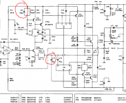
That's a blurry picture. Can you relate it to the Quad circuit and see what value its meant to be ?
Those type of caps rarely fail in my experience. 1000 at face value is 1000pf or 1nf.
I can quickly see two on the Quad circuit, one near the opamp and one across C and B of the lower output transistor.
Those type of caps rarely fail in my experience. 1000 at face value is 1000pf or 1nf.
I can quickly see two on the Quad circuit, one near the opamp and one across C and B of the lower output transistor.
Hi Mooly. Thanks for the reply.
I followed the tracks and noticed c5 and c10 may be acting as decoupling capacitors for the output transistors.
c5 right output transistor c10 left
If i wanted to add some extra decoupling could I solder a 100uf capacitor to the collector (case) of the output transistor, then run the negative of the 100uf capacitor to the respective c5 or c10
Thank you. John.
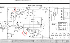
You are describing something totally different to what the circuit shows. C5 and C10 on my diagram aren't decouplers. Even on the first generation Quads they were labelled the same and as you can see, the collectors of the outputs mustn't under any circumstances be decoupled because they have circuitry in the collector feed from the rail (top output). And the lower output collector is the audio output.
Attachments
Hi Thanks for the reply.
Just checked, there is zero impedance reading on my meter, between the positive terminal of cap c5 and the right output transistor collector and also zero impedance between c10 and the left output transistor.
Thank you.
I can only go off what the circuit shows and it shows that those two caps are not decouplers. Replace them by all means but you must stick to the original values and points on the board they connect to.
Hi. Thanks for the replies
@Godfrey. I make it 0.03 ohms, may be my crappy meter
@Mooly Is it possible to place decoupling capacitors very near to the output transistors and / or driver transistors in some other I want to create a local power supply for the components to tap into, rather than having to wait for the main power supply.
Thank you.
The only place to add anything would be from the fuse/R35 junction to a suitable groun, and getting a correct ground point would be vital, otherwise you could be making things worse by injecting rail noise. If you look at the circuit there is decoupling from the emitter of the lower output. I would like to think there is a reason why its not done similarly for the top section too.
You need to be very very careful. Just adding parts in hope could reduce the overall performance.
You need to be very very careful. Just adding parts in hope could reduce the overall performance.
 .... correct is LME 49710
")
Years ago I noticed a similar effect exchanging the lm301 for an OPA27... Less noise and slightly better sound. I did talk about it with the Quad importer who was close to where I lived... even demonstrated it over a couple of ESL's and Q105'sYes you're right ofcourse, it is the LME49710 in TO8 metal can to be precise..
Typing on the iPad is sometimes a challenge
Leonard
Yes, it sounded better, but as they said "maybe due to some frequencies that were stronger" (no imbalance in the sound-image was noticeable, so that was nonsense)
Hi Mooly. Thanks for the reply.
Should the ground of the input phono sockets (screened cable input) of the quad 405 amplifier be connected to the chassis or not.
A the moment i have insulated the phono sockets from the chassis with a little piece of heat shrink cable and tested it with an ohmeter, there is no connection with either of the two cables within the phono cable with the chassis, and the amp works fine.
Many thanks. John.
Its usual for them to be insulated as you have done. If they are connected to chassis directly then there is every chance of a ground loop being formed.
However as always, you really should study and follow the original scheme because I wouldn't really expect the chassis to be "floating" with respect to these grounds either. Its usual for the chassis to make some direct (or at least low ohms) connection to the audio ground at some point on the amp although the original diagrams don't make that clear as to if/how it is achieved.
However as always, you really should study and follow the original scheme because I wouldn't really expect the chassis to be "floating" with respect to these grounds either. Its usual for the chassis to make some direct (or at least low ohms) connection to the audio ground at some point on the amp although the original diagrams don't make that clear as to if/how it is achieved.
- Status
- This old topic is closed. If you want to reopen this topic, contact a moderator using the "Report Post" button.
- Home
- Amplifiers
- Solid State
- quad 405 power amp advice