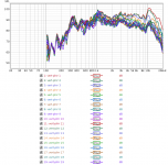
Here are the vertical measurements, done in the same style as before.
I don't have any measurements of the woofer box, but that's because I've not built it yet (just to clarify, in case anyone's wondering why I've not done that yet)") My intent was to build something that would match this horn with simple components (hopefully a first-order crossover), rather than build a box and then end up spending lots of time working around any incompatible characteristics.
My intent was to build something that would match this horn with simple components (hopefully a first-order crossover), rather than build a box and then end up spending lots of time working around any incompatible characteristics.
I don't have any measurements of the woofer box, but that's because I've not built it yet (just to clarify, in case anyone's wondering why I've not done that yet)
My intent was to build something that would match this horn with simple components (hopefully a first-order crossover), rather than build a box and then end up spending lots of time working around any incompatible characteristics.Attachments
So looking at the previous measurements, it's not obvious to me where the pattern flip occurs. Should I start building a box for the woofers, and then work on deciding the crossover point afterwards?
It also appears that I should build a box with one woofer above the other. I was kind of hoping to create a smaller box with the dirvers side-by-side, as it would sit under the horn quite nicely, but if that doesn't make sense for the sound, so be it
With a vertical arrangement, how wide should the sealed enclosure be? Earlier responses in this thread suggest the baffle should be physically wider than a frequency (the crossover frequency, perhaps).
Re Pattern Flip, you have quite a dense concentration of traces there, so it may be easier to see if you compare pairs of traces at a time.
I'd look at the pairs of matching angles in each plane, so 10o horizontal vs vertical, then 20o h vs v etc, that should make it much clearer where it's occurring.
HTH,
David.
I'd look at the pairs of matching angles in each plane, so 10o horizontal vs vertical, then 20o h vs v etc, that should make it much clearer where it's occurring.
HTH,
David.
Thanks David - that makes sense!Re Pattern Flip, you have quite a dense concentration of traces there, so it may be easier to see if you compare pairs of traces at a time.
I'd look at the pairs of matching angles in each plane, so 10o horizontal vs vertical, then 20o h vs v etc, that should make it much clearer where it's occurring.
HTH,
David.
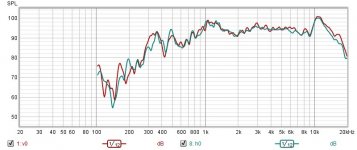
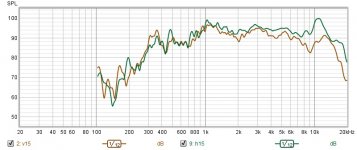
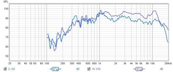
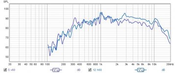
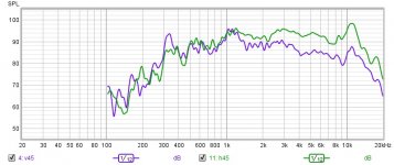
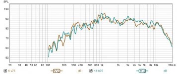
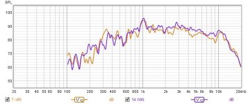
See attached. I've created individual comparisons between the horizontal and vertical angle plots, in 15 degree increments (REW complained at me when I tried to use all of my measurements).
From what I can deduce, at least up until the 60 degree mark, is that the pattern control is better horizontally above 1kHz.
What would the experts conclude with these plots, and is more information needed?
From what I can deduce, at least up until the 60 degree mark, is that the pattern control is better horizontally above 1kHz.
What would the experts conclude with these plots, and is more information needed?
Attachments
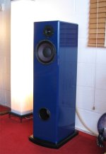
This update has been a long time coming, but I've finally completed building the midbass driver boxes:

Initially wired up they sound quite punchy, and appear to compliment the horn well. I'll try to get some measurements of them soon, so we can hopefully start building some crossovers!
Initially wired up they sound quite punchy, and appear to compliment the horn well. I'll try to get some measurements of them soon, so we can hopefully start building some crossovers!
By making the assumption that a good crossover frequency here would be 2kHz, the Dayton Audio XO2W-2K looks like a great candidate, especially as the 2 Alphas are running in parallel at 4ohms, and the GRS driver is running at 8.
Or would a 1.6kHz crossover, like in the Eminence PXB2:1K6 be more appropriate?
Thanks for your thoughts!
Or would a 1.6kHz crossover, like in the Eminence PXB2:1K6 be more appropriate?
Thanks for your thoughts!
Generic crossovers seldom result in what you hope for, but the 4/8 ohm woofer option on the XO2W-2K will give you more to play with.
The 1/3 octave difference between the two options listed is not a big deal, but the third order HF on the 1.6kHz PXB2 may be more of a problem with phase alignment.
The 1/3 octave difference between the two options listed is not a big deal, but the third order HF on the 1.6kHz PXB2 may be more of a problem with phase alignment.
Thanks @weltersys! Ah, third order - I missed that bit.
This inspired me to have a look for an online calculator. I ended up at https://www.diyaudioandvideo.com/Calculator/SpeakerCrossover/, plumbed the crossover values in, and it generated this for me:

Armed with this diagram, I took to Parts Express again, and found these components:
Apart from some protection circuitry, is that it?
This inspired me to have a look for an online calculator. I ended up at https://www.diyaudioandvideo.com/Calculator/SpeakerCrossover/, plumbed the crossover values in, and it generated this for me:
Armed with this diagram, I took to Parts Express again, and found these components:
Apart from some protection circuitry, is that it?
You posted a first order generic Butterworth crossover, which would have a +3dB bump at the crossover on axis (in addition to the bump the drivers may have) if the drivers happened to be the impedance of what you plugged in..Thanks @weltersys! Ah, third order - I missed that bit.
Apart from some protection circuitry, is that it?
A pair of Alpha 8A are not 4 ohms at 2kHz.
This thread would be helpful to get you started:
https://www.diyaudio.com/community/...igning-crossovers-without-measurement.189847/
Once again, thanks @weltersys. I can see now why @xrk971 recommended a 700Hz crossover point, given that the planar driver is practically the same impedance throughout its frequency range.You posted a first order generic Butterworth crossover, which would have a +3dB bump at the crossover on axis (in addition to the bump the drivers may have) if the drivers happened to be the impedance of what you plugged in..
A pair of Alpha 8A are not 4 ohms at 2kHz.
View attachment 1116028
This thread would be helpful to get you started:
https://www.diyaudio.com/community/...igning-crossovers-without-measurement.189847/
I'll continue to read @AllenB 's excellent thread, and try again
I've also been playing with VituixCAD which has been handy in getting an understanding of how the components affect the overall response.
Hi unaHm,
Congratulations on your horn and bass cabs - Inspiring workmanship! I too find these planar magnetics a worthwhile speaker partly because their frequency response naturally levels out when horn loaded.
Also, regarding the neo8 apparently the "peak the peak at 12khz won't 'ring'" or so Patrick Bateman suggested in a DIY mobile audio thread from 2012
https://www.diymobileaudio.com/threads/taming-the-neo8.126047/
So less of the harshness, perhaps, that can affect wide band cone drivers such as the Bastanis Chrystals, which I have and enjoy only with valve amplifiers, but still find a little "beamy".
I am thinking about one day building something like this:


This is a mini array with four BG Neo10s with twelve small ribbon PT mini-6 tweeters, with a single capacitor 6b/octave high pass filter at about 7 KHz.
This set up was by a Terry Marshal E. who posted it in the reviews section on the PT mini-6 in Parts Express https://www.parts-express.com/Dayton-Audio-PTMini-6-Planar-Tweeter-6-Ohm-275-083?quantity=1.
The BG Neo10s run full range. Terry, if your reading this, please tell us more, like what type of horn curve did you use?
My plan is similar but to use just two or three, instead of four, 10" planar magnetic drivers per speaker. This would give me sufficient sensitivity for flea watt amplifiers without making the array too long or expensive. Of course the BG Neo10 is no longer available. That leaves just two options, the GRS PT5010 or the much more expensive Radian LM10n. Which brings me to my observation/reflestion/question regarding your horn.
In a Joseph Crowe video:
"Speaker Plans for the BG NEO8S Front Horn (Summer Rain)"
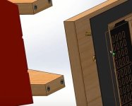
he mentions how critical it is to get the throat of the horn to the outside edge of the radiating holes/slots of his BG neo8. To illustrate, I have taken screen shots, with text, directly from his video:


Looking at your horn unaHm:


It may be that it could be improved by getting the throat closer to the outside slots, although this may be more hassle than its worth. One wouldn't know without trying.
Then my observation/question about the pesky little ridges which make it difficult to get as close to the holes as Joseph Crowe is suggesting:

Joseph Crowe seems to build his horn throats to accommodate the ridges:

Another solution might be to splash out on the Radian variants, which have no such ridges:


It would serve my needs and limitations better to work out a way to accommodate the ridges on the cheaper GRS PT planars. One could use a file or similar tool to make grooves to fit the ridges. Or use some sort of viscoelastic material as a gasket . If you, unaHm, or anyone else comes up with a solution or has one to suggest, I would be most interested.
Joseph Crowe, if your reading this, perhaps you could make an adapter that could make a flat surface for the DIYer to fit it to a horn of their own design?
Kind Regards,
Ben
Congratulations on your horn and bass cabs - Inspiring workmanship! I too find these planar magnetics a worthwhile speaker partly because their frequency response naturally levels out when horn loaded.
Also, regarding the neo8 apparently the "peak the peak at 12khz won't 'ring'" or so Patrick Bateman suggested in a DIY mobile audio thread from 2012
https://www.diymobileaudio.com/threads/taming-the-neo8.126047/
So less of the harshness, perhaps, that can affect wide band cone drivers such as the Bastanis Chrystals, which I have and enjoy only with valve amplifiers, but still find a little "beamy".
I am thinking about one day building something like this:
This is a mini array with four BG Neo10s with twelve small ribbon PT mini-6 tweeters, with a single capacitor 6b/octave high pass filter at about 7 KHz.
This set up was by a Terry Marshal E. who posted it in the reviews section on the PT mini-6 in Parts Express https://www.parts-express.com/Dayton-Audio-PTMini-6-Planar-Tweeter-6-Ohm-275-083?quantity=1.
The BG Neo10s run full range. Terry, if your reading this, please tell us more, like what type of horn curve did you use?
My plan is similar but to use just two or three, instead of four, 10" planar magnetic drivers per speaker. This would give me sufficient sensitivity for flea watt amplifiers without making the array too long or expensive. Of course the BG Neo10 is no longer available. That leaves just two options, the GRS PT5010 or the much more expensive Radian LM10n. Which brings me to my observation/reflestion/question regarding your horn.
In a Joseph Crowe video:
"Speaker Plans for the BG NEO8S Front Horn (Summer Rain)"
he mentions how critical it is to get the throat of the horn to the outside edge of the radiating holes/slots of his BG neo8. To illustrate, I have taken screen shots, with text, directly from his video:
Looking at your horn unaHm:
It may be that it could be improved by getting the throat closer to the outside slots, although this may be more hassle than its worth. One wouldn't know without trying.
Then my observation/question about the pesky little ridges which make it difficult to get as close to the holes as Joseph Crowe is suggesting:
Joseph Crowe seems to build his horn throats to accommodate the ridges:
Another solution might be to splash out on the Radian variants, which have no such ridges:
It would serve my needs and limitations better to work out a way to accommodate the ridges on the cheaper GRS PT planars. One could use a file or similar tool to make grooves to fit the ridges. Or use some sort of viscoelastic material as a gasket . If you, unaHm, or anyone else comes up with a solution or has one to suggest, I would be most interested.
Joseph Crowe, if your reading this, perhaps you could make an adapter that could make a flat surface for the DIYer to fit it to a horn of their own design?
Kind Regards,
Ben
Attachments
I finally stopped procrastinating and used the 2-way crossover website for 700Hz. I also modelled the crossover in XSim (as simple as it was), and the program suggested that I invert the polarity for the GRS horn as it gave a smoother response (no dip in the 'mid range' in the overall output).
I picked up some capacitors and inductors, and wired everything up. It sounds great!
Here are the values I ended up with:

Note, the value for L1 is derived for a 4-Ohm load, seeing as I had 2 Alpha 8a speakers in parallel.
I picked up some capacitors and inductors, and wired everything up. It sounds great!
Here are the values I ended up with:
Note, the value for L1 is derived for a 4-Ohm load, seeing as I had 2 Alpha 8a speakers in parallel.
Well done UnaHm!
What brand and type of inductors did you use? I don't know too much about them, but I've watched/heard Danny Ritchie bang on about air core inductors quite a bit.
What brand and type of capacitors?
What amplifier are you using?
Do you use a subwoofer or two?
How big is your room?
Matching a 4 Ohm load (the parallel combination of your woofers) with a 6.4 Ohm load (the GRS PT6825) is beyond my ken for now. Maybe you already posted it, but what is the "2-way crossover website" you used? Do you have pictures of your crossover you could post?
I was planning on using an active crossover (xKitz) with a single ended valve amplifier for the planar magnetic/s and a solid state amp for whatever woofer/s I end up using. I have an xKitz 2-way active crossover with plug in boards set to use at one of the following frequencies 500, 400, and 300Hz. Nevertheless using a passive crossover like you did also sounds like an excellent option.
Kind Regards,
Ben
For inspiration-here's a speaker Pi One using the Eminence Alpha 8a (coil only .5mh One woofer vs OP Two)
https://www.pispeakers.com/Measurements/onePi.html
https://web.archive.org/web/20171223233616/http://www.iol.ie/~waltonaudio/pione.html
https://www.pispeakers.com/Measurements/onePi.html
https://web.archive.org/web/20171223233616/http://www.iol.ie/~waltonaudio/pione.html
Attachments
Last edited:
Thanks Ben! Nothing really fancy went into the components list for these filtersWell done UnaHm!
What brand and type of inductors did you use? I don't know too much about them, but I've watched/heard Danny Ritchie bang on about air core inductors quite a bit.
What brand and type of capacitors?
What amplifier are you using?
Do you use a subwoofer or two?
How big is your room?
Matching a 4 Ohm load (the parallel combination of your woofers) with a 6.4 Ohm load (the GRS PT6825) is beyond my ken for now. Maybe you already posted it, but what is the "2-way crossover website" you used? Do you have pictures of your crossover you could post?
I was planning on using an active crossover (xKitz) with a single ended valve amplifier for the planar magnetic/s and a solid state amp for whatever woofer/s I end up using. I have an xKitz 2-way active crossover with plug in boards set to use at one of the following frequencies 500, 400, and 300Hz. Nevertheless using a passive crossover like you did also sounds like an excellent option.
Kind Regards,
Ben
For the High-pass filter for the GRS drivers, I used these in parallel:
1. https://www.parts-express.com/2.2uF-400-VDC-Audiophiler-MKP-Audio-Grade-Capacitor-020-636?quantity=1
2. https://www.parts-express.com/Dayto...0V-Polypropylene-Capacitor-027-421?quantity=1
3. https://www.parts-express.com/8.0uF-100V-Non-Polarized-Capacitor-027-338?quantity=1
For the Low-pass filter on the midbass box, I just went with:
https://www.parts-express.com/Dayto...AWG-Air-Core-Inductor-Coil-257-046?quantity=1
I'll have to check on the amplifier I'm using, but it's a Sony stereo amp from the 90s. It's definitely integrated!
I'm using two Bill Fitzmaurice T18 subs that have a 100Hz Low-pass filter on them, and I run those on a separate channel (the amp has A/B,A+B speaker selectors).
The room's not too large; I sit about 6 feet from each speaker as I'm kind of using them as monitors, but the back wall is a good 25 feet away.
Like you, I was going down the digital DSP route, but the sheer number of options caused me to procrastinate for too long, and buying discrete electronic components stopped me looking for reasons to buy computers or micro controllers that I might end up stealing for something else
Here's the online calculator I used: https://www.diyaudioandvideo.com/Calculator/SpeakerCrossover/
I hope that helps!
EDIT: I've just realised a mistake I've made. I was working on calculating filters for another set of speakers, and I put the tweeter in as 16Ohms, so 14.2uF is wrong. It looks like I need another 14.2uF! Doh!
Last edited:
- Home
- Loudspeakers
- Multi-Way
- Questions on Eminence Alpha 8a midbass box for indoor listening levels