I don't know what paper you mean, but the picture in post #2310 is clearly about a digital hardware IP. If it were software, they wouldn't specify the equivalent number of gates.
FPGA? To me the program loaded into an FPGA is Software.
Hardware IP would be something that requires Litho etc. But I am, telling this to the IC designer.
Ok, found the full bit of advertising:
https://docplayer.net/58384198-Axiom_pwmmod256fs1b-256fs-1bit-pwm-sigma-delta-modulator.html
"The IP deliverable consists of a RTL description in VHDL of the PWM sigma delta modulator."
"Synthesizable as ASIC logic or on FPGA"
Anyway, the point is that with a sigma-delta with embedded pulse width modulator, you don't need an RTZ DAC, if you implement the modulator such that there is always one and only one gap between adjacent PWM pulses.
DSD full scale is 0x77h / 0x44h. How do you place this "gap" of one BCK between each pulse?
Reading this:
the PWM ΣΔ modulator implemented on an FPGA and a DAC build from common off the shelf (COTS) components (a 74HCT574, 8 resistors, an Op-amp and an RC feedback network), an audio performance of 110dB dynamic range and 97dB SNDR MAX was measured.
This does not seem to compare particularly well with your DAC, which has the same basic structure.
And reading this:
"PWM frequency of 16*fS"
It would seem we are de facto dealing with a PWM output at 16fS (768kHz) embedded in a 256fS BCK domain?
This paper goes into a little more detail:
https://ris.utwente.nl/ws/files/211311186/Doorn2005audio.pdf
It seems three cascaded FIR are used, with a 128 TAP FIR for each. That is extreme even by the standards of 48 tap DSC2 type DAC.
Just thinking about the clock tree for that as a discrete DAC using 8 Bit Shift register IC's (96 X 74xx574 per balanced DAC) gives me severe headaches.
At that level of hardware, doing discrete is a non-starter and the performance?
A simple 2.5 USD COTS DAC Chip from 2003 considerably outperforms this.
I mentioned the DSD1700 before because t's structure is about the maximum I think is amenable for discrete implementation.
Each channel would 4 pcs 74xx574 and more or less something that parallel's the logic from your DAC, but a 4 X master and shift register clock.
To accommodate DSD256 this already needs a 1024 X MCK. A lot of logic doesn't do that well at 50MHz shift register clock for the FIR DAC.
Standard 74HC574 is rated ~120MHz typical clock, but in a FIR DAC I find performance degrades slightly past DSD128 and substantially at DSD256. This was testing NRZ DAC's and may be improved with RTZ, still tall order.
Using this ratio the logic needed for 574 may need 300MHz+ rated clock speed. That would mean NXP 74ALVC574, which seems the fastest "standard" part I notice.
With 8pcs 574 for two channels we already need to distribute our 1024X shift register clock to 8 IC's, with low jitter and clock skew.
Thor
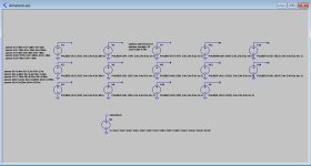
I make a subcircuit with various pulse generators that are added together in one sequence.As you can see from post #2313, despite claims to the opposite, there is nothing wrong with Marcel's interleaving so simulations of other models would not necessarily reveal any improvements.
BTW do you know if there is a better way to generate pulse patterns in LTSpice than what I used in post #2313?
Here is just an example where only amplitude and delay are put in parameters.
Behind logic circuits such as Gates and Flip-Flops I add another subcircuit with randomized Tr and Tf.
And to get a much better view on things in LTSpice, I use a BCLK that is at least 1/100 of the real clock.
See attachments.
Hans
Attachments
A Sigma-Delta PWM patent.
Some related patents:
https://patents.google.com/patent/US20070200742A1/en
https://patents.google.com/patent/KR101113468B1/en
Some related patents:
https://patents.google.com/patent/US20070200742A1/en
https://patents.google.com/patent/KR101113468B1/en
Attachments
Last edited:
Hans,
I have looked at it, but IIRC Marcel used a 27MHz clock (for understandable reasons), or was that only for the tube dac? Low phase noise 27MHz clocks don't appear to be COTS items. Custom crystals and oscillators would still be possible, but don't know if its worth the effort just to see how it sounds with a good clock.
Moreover, IIRC it was not RTZ. IME well-executed RTZ FIRDACs sound better than NRZ. IMHO the biggest problem with Marcel's RTZ dac is that most user implementations are not well-executed. There are other issues too, but hard to have motivation to fix those things when close to nobody cares to bother with a good user implementation. Maybe for most diy'ers its necessary to have a complete dac project including USB interface, clocking, power supplies, and layout to put it in case, because most people just won't do it by themselves at the level required to get the most out of the design. For one thing there isn't unified guidance as to what choices would lead to the best overall dac.
Last edited:
So where are we now in the discussion.
I don't have he impression that Marcel is eagerly waiting for a simulation of his Firdac.
And Thor, could you repeat in what respect to your opinion a dual interleaving dac is superior, in CM or in S/N or whatever aspect.
And last but not least we have this cross coupled system.
When dong a simulation, I should know at least what to look for, just simulating without a goal makes no sense.
Hans
Hans,
I have looked at it, but IIRC Marcel used a 27MHz clock (for understandable reasons), or was that only for the tube dac?
Both. My logic gate solid-state DAC was designed to be configuration-file compatible with my valve DAC, so the clock frequencies are the same.
Moreover, IIRC it was not RTZ.
It is RTZ, but JohnW had his doubts about the efficacy of the RTZ scheme I used - which eventually led me to design the RTZ shift register DAC.
Arrogant as always. I suggest you open a new thread on how to improve your Topolino dac.IMHO the biggest problem with Marcel's RTZ dac is that most user implementations are not well-executed. There are other issues too, but hard to have motivation to fix those things when close to nobody cares to bother with a good user implementation.

If someone goes to an oral hygienist to get their teeth cleaned or if someone merely reads comments by one, and if the message is that people should probably be using a gum stimulator in addition to flossing and brushing, would that be that arrogance?
I will leave off here on this subject.
I will leave off here on this subject.
And Thor, could you repeat
bohrok: "With this DAC there is unexpected rise of HD/IMD at high frequencies." (Observation)
Thor: "I think due to the RTZ nature of this DAC there is large common ripples at 1/2 SR_CLK." (Conjecture)
Thor: "I remember seeing that when I simulated the FIR DAC per MvG's design in TINA." (observation from possibly inaccurate memory)
Thor: " This may be the root cause." (Conjecture)
Thor: "Interleaving DAC's in a specific fashion can cancel this ripple and restore the the waveform to NRZ equivalent, retaining RTZ benefits."(Assertion / Induction / Observation)
MvG: "It's already interleaved." (Assertion)
Thor: "That depends on how we define interleaved. It is not interleaved in the precise manner suggested." (Observation)
bohrok: "Here a sim, I don't see anything." (Observation)
Thor: "I used a different simulator and just looking at the screenshots gives me headaches. I hate LT-Spice!" (Observation)
I think that about sums it up to now.
I do not think Simulations that can be set up sensibly will be able to really show most of the effects under discussion here, models are just not that detailed.
The best possible thing could be to confirm the presence of the common mode element at 1/2 SR_CLK or show that the FIR DAC in fact removes the ripple completely present in the RTZ Data Steam completely.
Thor
You are not an expert on how to implement Marcel's DAC (or any other DAC). If some members here do not follow you suggestions that does not make their implementation any worse. Rather the opposite.How do you say something which is true without someone feeling it is arrogant?
I'm quite sure you would get same results in Tina.
I would not simulate the way you do, fractional circuits. So my results cannot be expected to be the same.
Hating LTSpice does not change anything and I hate Tina.
It would change for me that I could take your circuit and add what is missing to get it to a point where it is sufficiently complete.
This is not about simulation models.
I don't have file around, I don't have the time now to recreate it right now.
Tell you what.
You win. All is well, there is nothing to improve on MvG's DAC, it is perfect.
Saves me the time to enter the whole DAC, setting the up logic models to be sufficiently accurate the analogue stage and all that and then run sims.
Thor
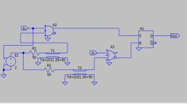
Could you be more specific. What part of the RTZ circuit is missing in post #2313?I would not simulate the way you do, fractional circuits.
Could you be more specific. What part of the RTZ circuit is missing in post #2313?
Output loading? For example. Most of the complete system.
Why not take a multichannel 'scope to the real circuit? Faster and you have the advantage over me of having actual circuit boards at hand.
You had a problem, I made a suggestion to investigate.
Take it or leave it. As you seem to have not investigated it, leave it.
Again, I'm done. I wasted too much time already.
Later Thor
Its too bad when one certain person can be so adept at derailing any potential progress when it comes to dacs.
MvG is doing mindboggling great work on DAC's, I am personally very grateful for what he has shared both in public and private. Especially seeing that he probably has a lot less spare time than a semi-retired beach bum (e.g. me).
Thor
Agreed about Marcel, he is a treasure to the forum. Also to give credit where it is due, although no longer in the forum Andrea Mori is doing some very good work with dacs intended for diy use. And Acko was able to get some clearly SOA dac clocks manufactured and available for sale. So, yes, there are people doing some good work. However IMHO in a practical sense, Andrea is overall ahead of everyone else at this point. I know he learns from Marcel like we all do. What makes Andrea different is he is driven to making constant progress. And as they say in the music business, "he has ears."
Last edited:
- Home
- Source & Line
- Digital Line Level
- Return-to-zero shift register FIRDAC