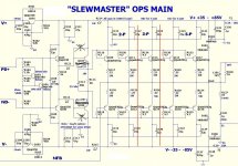
Here it is.Can you please drop the schematic here? Looks like a local OPS oscillation ti me.
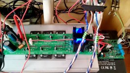
Mine is a test board with one pair 2sc5200,2sa1943 installed.
All Ostriper's IPS,CFA&VFA tested on this board.
Attachments
Last edited:
Here it is.
Mine is a test board with one pair 2sc5200,2sa1943.
No attachment?
")
Hi Thimios,
I ran simulation of Vertical CFA front-end with Slewmaster OPS.
Slewmaster adds a pole at 6.7MHz, which is not the case with NS-OPS, allowing lighter compensation, than Slewmaster would require.
Please make C12, C15 = 100pF - this should eliminate that pole's influence on amplifier stability.
Cheers,
Valery
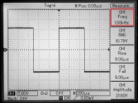
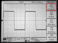
6.7MHz! Exactly what the frequency counter measuresHi Thimios,
I ran simulation of Vertical CFA front-end with Slewmaster OPS.
Slewmaster adds a pole at 6.7MHz, which is not the case with NS-OPS, allowing lighter compensation, than Slewmaster would require.
Please make C12, C15 = 100pF - this should eliminate that pole's influence on amplifier stability.
Cheers,
Valery
I will try this solution and report again.
I hope this wouldn't make this IPS slow.
6.7MHz! Exactly what the frequency counter measures
I will try this solution and report again.
I hope this wouldn't make this IPS slow.
You should build the output boards that go with. It works great with those.
I know Jeff but this will be a long travel because many of parts missing.You should build the output boards that go with. It works great with those.
I know Jeff but this will be a long travel because many of parts missing.
Make a list of what you're missing. We need a good tester to try this out for us!
!!!!!!!!Make a list of what you're missing. We need a good tester to try this out for us!

I will do the best!

Where i can see a bom?
Last edited:
Unfortunately this IPS refused to marry the slewmaster.Hi Thimios,
I ran simulation of Vertical CFA front-end with Slewmaster OPS.
Slewmaster adds a pole at 6.7MHz, which is not the case with NS-OPS, allowing lighter compensation, than Slewmaster would require.
Please make C12, C15 = 100pF - this should eliminate that pole's influence on amplifier stability.
Cheers,
Valery
Problem is exactly the same
Unfortunately this IPS refused to marry the slewmaster.
Problem is exactly the same
Thimios, you can try to increase C24, C35 (22, 33, 47pF) and / or C18, C19 (47, 68, 100pF). In general, this is rather odd...
Ok i will try this soon.Thimios, you can try to increase C24, C35 (22, 33, 47pF) and / or C18, C19 (47, 68, 100pF). In general, this is rather odd...
I have some objections to the quality of mine 2N5401
Is this something that can affect the stability?
VERTICAL VFA - another cool option
Guys, yesterday another idea came to my mind.
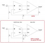
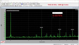
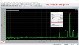
Since NS-OPS is a rather low-distortion one, why don't I try to exclude the OPS from the global NFB loop? The first picture outlines the "traditional" GNFB arrangement (upper scheme) and the one I just mentioned (lower scheme).
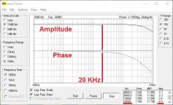
I have just removed the global NFB resistor and the lead compensation cap from the front-end board and added two resistors and two smaller lead caps underneath the board. The only feedback, connected to the OPS output is DC servo now.
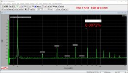
You can see the measurements. Harmonics profile is "longer" now for sure - we see higher order components, however, their absolute level is low enough. It's still a "CFA-fast VFA", performing very accurate transients handling and low IM distortion.
Sound-vise, I notice less speaker damping an the low frequencies - bass is still punchy, but a little bit "softer" - on some tracks sounds even more pleasant, than the tightly-controlled one. Mids and highs are as detailed as they were before, however, there is some barely recognizable "signature" here. Difficult to say, what exactly it is - I'm listening to one channel now - but it seems to me, the tone balance is just very slightly different.
If I would have an A/B testing system, as good as Terry has - I would probably be able to have a clearer comparison. Anyway - worth trying!
Cheers,
Valery
Guys, yesterday another idea came to my mind.
Since NS-OPS is a rather low-distortion one, why don't I try to exclude the OPS from the global NFB loop? The first picture outlines the "traditional" GNFB arrangement (upper scheme) and the one I just mentioned (lower scheme).
I have just removed the global NFB resistor and the lead compensation cap from the front-end board and added two resistors and two smaller lead caps underneath the board. The only feedback, connected to the OPS output is DC servo now.
You can see the measurements. Harmonics profile is "longer" now for sure - we see higher order components, however, their absolute level is low enough. It's still a "CFA-fast VFA", performing very accurate transients handling and low IM distortion.
Sound-vise, I notice less speaker damping an the low frequencies - bass is still punchy, but a little bit "softer" - on some tracks sounds even more pleasant, than the tightly-controlled one. Mids and highs are as detailed as they were before, however, there is some barely recognizable "signature" here. Difficult to say, what exactly it is - I'm listening to one channel now - but it seems to me, the tone balance is just very slightly different.
If I would have an A/B testing system, as good as Terry has - I would probably be able to have a clearer comparison. Anyway - worth trying!
Cheers,
Valery
Attachments
Another "old" possibility as an alternative FB method:
The ALTMANN SPLIF Amplifier Topology
Or you can adjust it to the "middle" with a (0 - 1R) resistor between the protected pair and the load driver pair(s).
The ALTMANN SPLIF Amplifier Topology
Or you can adjust it to the "middle" with a (0 - 1R) resistor between the protected pair and the load driver pair(s).
It reminds me my efforts to get my own audio nirvana:
at first I biult SET - excellent sound
then EL34PP ~ similar
then ngnfb ss amps - so so OK
classic ss vfas - fatiguing
ss cfas - better as vfas
2 mosfet transconductance amp - excellent
LM1875 GNFB transconductance chip amp - like SET
last one curied me from thinking that gnfb is bad for audio
at first I biult SET - excellent sound
then EL34PP ~ similar
then ngnfb ss amps - so so OK
classic ss vfas - fatiguing
ss cfas - better as vfas
2 mosfet transconductance amp - excellent
LM1875 GNFB transconductance chip amp - like SET
last one curied me from thinking that gnfb is bad for audio
- Home
- Amplifiers
- Solid State
- Revisiting some "old" ideas from 1970's - IPS, OPS