I use the ‘1nF caps’ as standard and the recommended RFI for example on the THAT drivers/receivers. I have never, ever had an RFI problem.
“I did, got distracted. It comes from the same 2 in sqrt(2qI), the collector shot noise. There is still a problem with all these sims being posted with nonsense models.”
Well, I will just rerun them again with the improved data. The absolute noise numbers are nonsense, but they will give a comparative yardstick between the various topologies
Well, I will just rerun them again with the improved data. The absolute noise numbers are nonsense, but they will give a comparative yardstick between the various topologies
A slight correction to the above because your 0.28nV/rtHz is without input resistor.But my experience is that there are still situations where fully balanced is advantageous.
________________________________
May I conduct a little poll ?
We've had loadsa sims but how about real life examples, actually in use in vinyl playback systems. I've got 280pV/rt(Hz) and I think Wayne has 500pV/rt(Hz) in his balanced system .. both measured as well as simmed.
Any more real life examples?
Wayne has measured 0.49nV/rtHz and the Sim with the adjusted 1R5 Rb showed 0.57nV/rtHz, both still with the 10R source and 1R Rg. When taking both resistors out (10R5) , measured would become 0.25nV/rtHz and simmed 0.39nV/rtHz.
I'll come back to that later today, because things are a bit more complicated.I really want someone to build both my circuit as well as the modded JC to compare. I'm pretty certain I tried out JCs topology circa 1980 but can't remember what the cons were. Probably to do with EVIL 1000uF caps but I'm guessing from 40 yrs on.
http://www.hoffmann-hochfrequenz.de/downloads/lono.pdf is the only example of measured performance that's sorta pukka. It is, in theory, 0.9dB quieter than mine on the LoZ MCs .. but slightly more complex. Not sure if anyone has tried it on a MC system.
____________________________
Hans, may I ask you label your JC results 'JC modded by Lee'. Guru Wurcer will insist my circuit be labelled 'Leach modded by Lee'. I only improved JC's noise by 4.4dB while I got more than 10dB with Leach 😱
Hans
Here it is:
Thanks for the sim.
The 15 µV sims seem to be incorrect as both tables are exactely the JC 5µV values.
This is what attracted me to the topology. It's been around 50 years in all sorts of INA applications and in countless studios providing gain for the music we all love, so 'battle proven'. I don't need the Cohen cross-couple output stage, but it doesn't hurt. Irrational choice but most things phono are 😀That circuit BTW was published in 1968 by Bob Demrow .
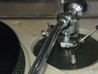
SME learned the error of their ways. My 309 has a 5 pin connector and STP wiring back to the preamp. My 3009 does have the can and RCA setup, which might be just the right size for your headamp.[/quote]In da old days, many Old World tone arms and preamps used 5p DIN connectors which allowed you to do this (4 cores & screen) right up to the cartridge. Not sure about da rebel colonies.
It was SME which made this unfashionable cos they introduced their EVIL Gold Plated (but crap 😱) RCA phono cables which became sorta standard in high quality tone arms.
Sad that people are prepared to spend $$$ on supadupa mains cables etc but won't spend 2c on something which actually makes things sound better 🙁 ... not that I'm accusing you Bill. 🙂
I just don't like waste! And Brasso is useful. And I get my mains cables out the skip at work!
Given this armbase I'm thinking of direct attachment.You build the circuit including the attached C cell battery holder into the lid of the Duraglit tin.
Attachments
A slight correction to the above because your 0.28nV/rtHz is without input resistor.
Wayne has measured 0.49nV/rtHz and the Sim with the adjusted 1R5 Rb showed 0.57nV/rtHz, both still with the 10R source and 1R Rg. When taking both resistors out (10R5) , measured would become 0.25nV/rtHz and simmed 0.39nV/rtHz.
In general specifying referred to input noise without a source resistance is meaningless. You have to account for current as well as voltage noise i.e. the practice of specing noise of MM pre-amps with input shorted.
I won't tell you who made this mistake (not me) on a datasheet and I had to correct it.
Is input noise current an issue on bipolar input amplifiers with MC source resistances of 10-20 Ohms?
Different story for MM of course and something JA has missed on his phono amp test regime for Stereophile.
Different story for MM of course and something JA has missed on his phono amp test regime for Stereophile.
Is input noise current an issue on bipolar input amplifiers with MC source resistances of 10-20 Ohms?
Yes, when you discuss paralleling devices ad nauseum as a solution or running a common emitter circuit at 100mA Ic. We are also including common base circuits.
I couldn't agree more, but when comparing amps one should compare apples to apples, which was not the case at that moment.In general specifying referred to input noise without a source resistance is meaningless. You have to account for current as well as voltage noise i.e. the practice of specing noise of MM pre-amps with input shorted.
Extremely low noise figures without source resistances are indeed rather meaningless, so are S/N figures of over 75dB with the source resistance connected IMHO.
Hans
H&H ran their mic amp at 100 mA IC for < 100 pV/rt Hz.
I can see that Gerhard’e 20 op amps in parallel is a problem.
I can see that Gerhard’e 20 op amps in parallel is a problem.
Thank you for noticing this silly error, no idea what happened.Thanks for the sim.
The 15 µV sims seem to be incorrect as both tables are exactely the JC 5µV values.
Anyhow, here is the correct table, all values have been checked now.
Hans
Attachments

No. My 1980 measurement of 0.28nV/rt(Hz) was with a 5R (IIRC) resistor.A slight correction to the above because your 0.28nV/rtHz is without input resistor.
Since the 1981 WW SC noise figures, I probably only measured Short Circuit noise on that circuit when trying to estimate rbb'.
Instead of 'taking the resistor out', the correct approach is to determine Noise Factor, which is how much the preamp degrades the source resistor noise. After all, that's what we are really interested in.
Certainly for the common base amps .. which is why I'm so pedantic about matching.Is input noise current an issue on bipolar input amplifiers with MC source resistances of 10-20 Ohms?
But loadsa designs have other noise sources that make this moot. When you get down below 5R source, even the best designs are struggling to run enough current through a single device (pair) and the noise current goes through rbb' too.
I'd better not simplify things too much cos Guru Wurcer will make me stand in the corner 🙂
Damn!! I've improved JC until it has 0.8 to 0.5dB better THD than mine 😱Thank you for noticing this silly error, no idea what happened.
Anyhow, here is the correct table, all values have been checked now.
Should have kept my mouth shut 😡
_________________________
Though I describe the genesis of my circuit from Leach in the MicBuilders doc, I actually saw that topology much earlier in a very early 1960s Philips book on da new-fangled transistors that had just been invented by Bell Labs. One of those textbooks that showed circuits with both ends of the power supplies earthed. It postulated the possibility of complementary devices 😱 and how they might be used.
They thought transistors should be 'current driven' so common base was much favoured.
I really didn't understand any of it as I was playing with crystal sets. An AF116 came in a little cardboard box and cost a week's pocket money. Fortunately, a bit later, I found you could salvage loadsa good transistors from dead transistor radios 🙂
Last edited:
Don't worry too much - for the higher input amplitudes you are the winner and also when looking onto the higher harmonics🙂
So it would be nice to see real circuit measurements for both circuit topologies side by side using same measurement setup and equipment (and maybe even using the same transistor pair). Spice sims are nice and helpful but real life might be a different story.
So it would be nice to see real circuit measurements for both circuit topologies side by side using same measurement setup and equipment (and maybe even using the same transistor pair). Spice sims are nice and helpful but real life might be a different story.
H&H ran their mic amp at 100 mA IC for < 100 pV/rt Hz.
.
I would file that under 'heroic parallisation' though...
H&H ran their mic amp at 100 mA IC for < 100 pV/rt Hz.
Yes the ribbon IIRC << 1 Ohm a perfect example. The Delft example was 25mA for the 3 Ohm Ortophon.
I checked the THAT Corp. website their process showed a 30 Ohm Rb and 2 Ohm Re NPN (PNP's will usually be a little lower) for a transistor about 32sq. mils so 32 of these in parallel would bring you 1 Ohm at ~1000 sq. mils. Two of these in an SOT should be easy. The problem would be the fact that the Is ratio can be large (ours was 3:1) and not tightly controlled so the Vbe match is problematic. These are their array transistors that do 0.9nV or so which seems to be where the IC solutions have found a sweet spot (yes, it's less than 1 😉).
Last edited:
They run the Ic at 100mA on a single ZTX851 to get 70 pV/rt Hz - the source impedance (ribbon mic) is 0.1 Ohm) - see page 506 AoE Ed. 3.
But, the input Z is very low so you need a 150mF input coupling cap which of course is absurd and they recognize this. A differential pair gets rid of the cap but you pay a 3dB noise penalty. Tail current is 200mA (!).
These are interesting circuits but exercises in self-flagellation in many respects.
I'm working through this at the minute http://www.eng.auburn.edu/~wilambm/pap/2011/K10147_C011.pdf
These are interesting circuits but exercises in self-flagellation in many respects.
I'm working through this at the minute http://www.eng.auburn.edu/~wilambm/pap/2011/K10147_C011.pdf
Transistors MAT-2 from Analog Devices (monolithic transistor pair) have β = 500 and rb below 1 Ω.
🙄 That's Re (log conformance) otherwise the Ein at 1mA would be 0.5nV or so.
Last edited:
- Home
- Source & Line
- Analogue Source
- Richard Lee's Ultra low Noise MC Head Amp