You probably have read the documentation, as in hificollective ?
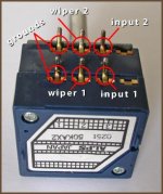
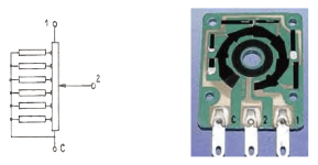
pin 1 is input, pin 2 out, C (or 3) GND...
(I don't know about which is 1 or 3, would adhere to the standard, like for the Alps…)
If this is/was not the problem, I'm out of context…
pin 1 is input, pin 2 out, C (or 3) GND...
(I don't know about which is 1 or 3, would adhere to the standard, like for the Alps…)
If this is/was not the problem, I'm out of context…
Attachments
A year later I caught up on DCG3. First power on everything clear, nothing suspicious, measurements ok. After 15mins and VR1 adjustment 0 DC offset without and with the opamp. Temperature inside the heat sink (about 40 minutes powered on is 43C), in open space as in the photo. First impression regarding sound, I could not thank you more! ")

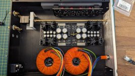
Thanks cyberpup, will do (although I cannot detect any hum with the headphones). This is a temporary connection, to test things. Among others, I have to tidy up cabling a bit, raise the volume pot to fit in the face plate and complete the remote control and VU meters connections. I am concerned a little about the temperature though, maybe I will have to resort to a larger sink.
Yes at a speaker power output. Fingers crossed it is still working fine

Better not borrow from your DCSTB 17.6V regulated output. Not to mix a potentially interference prone line.
At underside DCSTB 2200uF C2's pins you will find +V/0V raw DC points to tap. Will almost certainly measure higher than 24V given your mains & transformers.
Put a 10k resistor in series with the switch's red or black thinner wire feed to its LED so to protect it.
Or a 20k trimmer wired like a rheostat (adjustable series resistor) to can control your preferred brightness. Start from midpoint trimmer setting before power on.
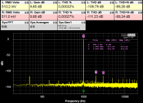
Is that the QA403 analyzer? Has about -110dBV THD+N own loop resolving ability at 1 VRMS I see on the maker's screenshots.It seems to have worked. I attach photos of the cable and the measurements .
Your 1V RMS measurements with the DCG3 in the loop are squeaky clean with this special SE-->BNC BAL Star-Quad you made.
But what it also shows with the DCG3 in the loop when at 0.5VRMS?
We usually measure at 0.5V RMS output too in this thread for a closer to practically loud listening levels volume pot position.
Good morning. Is this correct?
All wires twisted.
Not showing the potentiometer yet, want to figure out the mains first. I understand the fuse can be added as per Salas's comment before the switch, will use the fuse tray in the inlet for now. Grounding: should I ground IEC heart tho chassis and link each board, transformer shield and potentiometer to a single point? Thank you
Fuse after the switch if with a standalone round fuse holder is my preference.
Fuse tray in IEC puts it before switch but no big deal because it slides out safely.
Regarding your wiring plan I would rather exchange red with black secondary wires in the diagram.
Connect IEC center pin to chassis nearby with short thick cable and safety nut. Transformer shield wires go there too.
Scratch box panels at mating points for good contact between them if anodized and obstructing electrical continuity.
From boards and potentiometer don't link any ground points to chassis as yet. It may prove working noiseless without.
Yes. This is QA403.Is that the QA403 analyzer?
And here is measurement for 500mv output.
Attachments
- Home
- Source & Line
- Analog Line Level
- Salas DCG3 preamp (line & headphone)