
Hi Everyone, revised boards have been ordered. I am getting 10 for now. Use this sheet to register your interest.
Note that this is the buffer board intended to be connected to the main board. If you are looking for the main SCG board, there is a new one coming.
And thanks for the patience everyone.
Note that this is the buffer board intended to be connected to the main board. If you are looking for the main SCG board, there is a new one coming.
And thanks for the patience everyone.
Last edited:
Upgrade your existing preamp!
A few changes are coming in the new design. If you already have a built preamp (or are sitting on PCBs), you can transition it to the new design. Here is Part I of the changes. Part 2 requires some desoldering, so we'll save it for later. These changes you could do in less than 5 minutes and also revert them back in 5 minutes. The subjective impact is more open sound and clearer highs while still retaining the original sound.
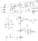
See attached schematic. There are two changes to make:
1. Make Vg on the bottom FET (Q102) equal to zero volts. This is done by turning RV103 and measuring zero volts at Vg to ground. Vs should measure something like 4 volts.
2. Next, we want to skip the capacitor and resistor that biases the voltage of the gain FET Q101. Place a wire across RV102 or C102 or C102byp, whichever is easiest. C102byp might be easiest to get to. That's what I did. You can tie it together with alligator clips for testing.
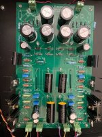
Measure Vd. It should read 80-85V. Note that you want a good chunk of heatsink on Q101 because now it is dissipating 80V x 25 ma = 2W. I installed one on my Q101. See the image below.
The main objective with the two changes is to directly connect Rg to ground instead of through C102. When you connect Rg to ground (in step 2), it puts the gate of Q101 at 1/10th the voltage of Vd. Given that Vs = 4V and the Q101 Vgs is also about 4V, for a total of 8V, times 10 equals about 80V. If you didn't do step 1, then you will end up with Vd higher than 100V and it will not work.
Note also that if your supply is 100V (top of Q103), then you are limited to about 15-20V of output swing in the positive direction. Most cases this will be fine. If you need more swing, then you can raise the supply voltage by increasing the voltage of the zener string to above 100V. This assumes you have at least 7V of clearance on the regulator. For example, if you wanted to go from 100V to 115V, then you want the drain of Q11 to see 115+7 = 122V.
Have fun and tell us what you hear!
A few changes are coming in the new design. If you already have a built preamp (or are sitting on PCBs), you can transition it to the new design. Here is Part I of the changes. Part 2 requires some desoldering, so we'll save it for later. These changes you could do in less than 5 minutes and also revert them back in 5 minutes. The subjective impact is more open sound and clearer highs while still retaining the original sound.
See attached schematic. There are two changes to make:
1. Make Vg on the bottom FET (Q102) equal to zero volts. This is done by turning RV103 and measuring zero volts at Vg to ground. Vs should measure something like 4 volts.
2. Next, we want to skip the capacitor and resistor that biases the voltage of the gain FET Q101. Place a wire across RV102 or C102 or C102byp, whichever is easiest. C102byp might be easiest to get to. That's what I did. You can tie it together with alligator clips for testing.
Measure Vd. It should read 80-85V. Note that you want a good chunk of heatsink on Q101 because now it is dissipating 80V x 25 ma = 2W. I installed one on my Q101. See the image below.
The main objective with the two changes is to directly connect Rg to ground instead of through C102. When you connect Rg to ground (in step 2), it puts the gate of Q101 at 1/10th the voltage of Vd. Given that Vs = 4V and the Q101 Vgs is also about 4V, for a total of 8V, times 10 equals about 80V. If you didn't do step 1, then you will end up with Vd higher than 100V and it will not work.
Note also that if your supply is 100V (top of Q103), then you are limited to about 15-20V of output swing in the positive direction. Most cases this will be fine. If you need more swing, then you can raise the supply voltage by increasing the voltage of the zener string to above 100V. This assumes you have at least 7V of clearance on the regulator. For example, if you wanted to go from 100V to 115V, then you want the drain of Q11 to see 115+7 = 122V.
Have fun and tell us what you hear!
Attachments
Next, we want to skip the capacitor and resistor that biases the voltage of the gain FET Q101. Place a wire across RV102 or C102 or C102byp, whichever is easiest.
I will desolder all 3 of RV102, C102 and C102byp and add a wire in place of C102byp. Later today.
I don’t remember if my heatsink is that beefy on Q101, so, I’ll check that too.
You could try it out before desoldering and see if you like it. Simply connect the two legs of C102byp together using an alligator clip. If you like it, then desolder.
I have faith. It'll be great and this is the way.


Make Vg on the bottom FET (Q102) equal to zero volts. This is done by turning RV103 and measuring zero volts at Vg to ground. Vs should measure something like 4 volts.
I can't get down to 0 volts. Mine goes 0.8 millivolts on one side and 4.1 millivolts on the other side. VS is closer to 5 volts. Is this okay to move on?
- Home
- Amplifiers
- Pass Labs
- Schade Common Gate (SCG) Preamp