So, I put a big heat sync on Q101. I got Vg as low as I could go as per my previous note. Vs is at about 4.9 volts. I pulled C102Byp and soldered a wire instead. However, Vd to ground is measuring about 48 volts; nowhere near the 80 volts you specified. Do I need to make another adjustment?
Edit - Now I remember I lowered my gain to around 6X. Maybe that has something to do with my lower voltage reading.
Thanks,
Alan
Edit - Now I remember I lowered my gain to around 6X. Maybe that has something to do with my lower voltage reading.
Thanks,
Alan
Last edited:
Yeah, with the VFET amp, it makes a difference.
Is the BOM for the buffer board finalized? 🤑
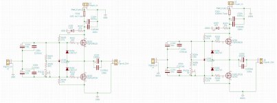
Hi can you post a schematics of your Version?Hi Mr. Ra7, here my Power Amp version of your SCG
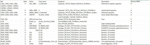
Here's the BOM and revised buffer schematic. Also, see here for a Mouser cart. It does NOT have resistors but has everything else.Is the BOM for the buffer board finalized? 🤑
https://www.mouser.com/ProjectManager/ProjectDetail.aspx?AccessID=e930f0fd0e
Please don't make changes to the Mouser BOM/project. Let me know if something looks amiss.
P-channel MOSFETs are a rarity in Mouser right now. I picked two (N and P) that appear to be a fair choice, but have not tried them because I have FQP19N20 and FQP12P20. Any good pair of complementary MOSFETs will work as long as the minimum Vds is greater than 60V or so. The buffer is a push-pull follower operated in Class A and so most complementary pairs will work just fine.
Attachments
Last edited:

I've spent a couple days listening to your modification. I haven't yet tried reversing phase internally yet.Have fun and tell us what you hear!
I think this version sounds smoother and hence more long term listening friendly. The original version, at least in my system, had great bass but accentuated the frequencies around upper-mid piano harmonics a bit too much for my sense of musical relaxation. I know that sounds ridiculous, but that's how I would describe the sound. The new circuit still has a fair amount of presence in those frequencies, but sounds cleaner.
It still sounds more like a tube preamp than a solid state preamp. The mids are pushed forward a bit, so maybe I'll try your phase suggestion. Overall though, I like the sound better now. Looking forward to your next suggestion.
I've recently completed SCG board. It powers up OK but CCS current can't be adjusted beyond 0.114A (114mV across R107) using RV101. Correct operating points for Q101 and 102 (20-30V and 65V respectively) can be set using RV102 and RV103. Voltage on load at TP4 is around 115V. Q11, 101, 102 and 103 have substantial heatsinks but get very warm (untouchable) within less than ten minutes of switch on. Zener stack is 121V (100, 15, 6.2) and all other components for a standard build (gain of 10X) are as per BOM, with the exception of Q102, which is FQPF7P20.
I suspect something is wrong - any ideas, or suggestions would be welcome.
Thanks.
I suspect something is wrong - any ideas, or suggestions would be welcome.
Thanks.
Hi marconi118, sent in pmHi can you post a schematics of your Version?
Upgrade Part II
This change requires desoldering the gain device and installing a new one in its place. We are going from an FET to a BJT here, the part being the ubiquitous BC550 (C or B version). The subjective impact is that the preamp sounds much more relaxed in the highs and the 3D-ness and palpability are better.
Looking at the FET and BJT from the front, the pins are:
FET: G-D-S
BJT: C-B-E
The C and B pins have to be interchanged prior to installing on the PCB. There are various ways to do this and I leave that up to you guys.
Here are the steps:
Part A: Replace gain device.
1. With the current FET in place, lower the current through the CCS to 10 mA.
2. Switch out the FET for the BC550, remembering the different pinout of the new part.
3. Measure Vd, it should be a little higher than Vs x 10 (in reality, about (Vs+0.7)*10). With the FQP12P20 or similar MOSFETs, Vs will be about 4-5V, meaning Vd will be 47-57V.
Part B: Replace bottom/input FET
The BC550 is a 45V part, and with the change in Part A, we're operating it right at the dissipation limit. Plus, the FQP device (a TO-220 part) in this configuration adds a bit of thickness to the sound, which could work well with other system components. But I found that other MOSFETs in TO-92 packages (VP0106, VP0104, TP2640) and even the 2sk74 or LSJ74 JFET are a better fit. They generally have much lower input capacitance. So, if you have these on hand, make the change.
If you put in 2sj74, then RV103 should be used to set Vs to 3.5-4.5V. If using MOSFETs, leave Vg at or near zero volts. Remember that Vd will be approximately 10 times Vs. Don't push the BC550 beyond 55-57V Vd.
There are other changes coming on the new PCB, including improved CCS, better power supply, and of course the buffer. The buffer really helps with the BC550, which has a much lower dissipation capacity. Given that we want to swing 40V in one direction, the max current through BC550 is limited to 7-10 mA. That works just fine but a buffer gives it superpowers and plus you can drive headphones directly.
Other parts, including the KSC1845, will also work fine, though my personal preference is the BC550. But throwing different devices in is a fun exercise.
- Home
- Amplifiers
- Pass Labs
- Schade Common Gate (SCG) Preamp