Stereo HY69 amplifier
When I first saw a photo of an HY69 tube, I decided I needed to make an amplifier using it. So last Spring during lock down I decided to make an amp out of parts I had on hand that I had been collecting for years and had always intended to use "some day."
The HY69 is a bit challenging to use because it is a directly heated pentode. I decided that separate filament transformers for each tube could achieve the lowest hum, so I treated them just like a 2A3 with individual hum pots and individual cathode resistors. As it turned out the amp is very quiet.
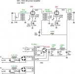
The rest of the amp is pretty conventional with the Mullard 5-20 as the inspiration using a 12BY7 voltage amp into a LTP of 6F8G with a CCS tail. The screen grid of the 12BY7 is regulated by a couple of zeners and the screen grids of the HY69 are regulated by a couple of 0D3 VR tubes. It employs conventional GNFB of about -16dB. The power supply is 475V @ 300mA.
I had a pair of Sansui H30-6 output transformers I had scrounged on eBay in separate auctions a few years apart that I was very anxious to put to use. I figured the 6.6k impedance was a bit low from the data-sheet linked above, but when I put my 16r speakers on the 8r tap it sucked the life out of the music. Apparently, the 6.6k impedance works well in since I truly love the sound of this amp. It can achieve a clean 12W per channel in the current setup.
I know that there are some refinements I could make in the implementation of the 5-20 circuit, but right now I am afraid to fiddle with it since I don't want to mess up whatever is working so well.
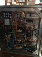
Note: the amplifier chassis was "recycled" but the power supply chassis was made by Landfall Systems during August.
When I first saw a photo of an HY69 tube, I decided I needed to make an amplifier using it. So last Spring during lock down I decided to make an amp out of parts I had on hand that I had been collecting for years and had always intended to use "some day."
The HY69 is a bit challenging to use because it is a directly heated pentode. I decided that separate filament transformers for each tube could achieve the lowest hum, so I treated them just like a 2A3 with individual hum pots and individual cathode resistors. As it turned out the amp is very quiet.
The rest of the amp is pretty conventional with the Mullard 5-20 as the inspiration using a 12BY7 voltage amp into a LTP of 6F8G with a CCS tail. The screen grid of the 12BY7 is regulated by a couple of zeners and the screen grids of the HY69 are regulated by a couple of 0D3 VR tubes. It employs conventional GNFB of about -16dB. The power supply is 475V @ 300mA.
I had a pair of Sansui H30-6 output transformers I had scrounged on eBay in separate auctions a few years apart that I was very anxious to put to use. I figured the 6.6k impedance was a bit low from the data-sheet linked above, but when I put my 16r speakers on the 8r tap it sucked the life out of the music. Apparently, the 6.6k impedance works well in since I truly love the sound of this amp. It can achieve a clean 12W per channel in the current setup.
I know that there are some refinements I could make in the implementation of the 5-20 circuit, but right now I am afraid to fiddle with it since I don't want to mess up whatever is working so well.
Note: the amplifier chassis was "recycled" but the power supply chassis was made by Landfall Systems during August.
Attachments

Last edited:
"If you have 5K transformer and 400W then with 40mA anode current you could get up to 4W. A1 or A2 will depend on bias. So what you need to do in practice is start using self bias and adjust the cathode resistor until you find the best solution. I am just guessing that for 400V anode voltage and 40-45mA current you bias should be around 40-45V (negative). So you can start with 1K cathode resistor and bypass with a good capacitor. The if your current is too high (low) you increase (decrease) the resistance until you find the solution that gives you max Pout (also keep an eye on distortion...).''
45...the above is about hy69 or 814. I am more interested in hy69 because of lowish filament power, I live in a hot country. If you help me I can realize my dream. 3 watt Se power is fine with me. Please help.
Regards
45...the above is about hy69 or 814. I am more interested in hy69 because of lowish filament power, I live in a hot country. If you help me I can realize my dream. 3 watt Se power is fine with me. Please help.
Regards
Sandy...very nice build, congrats! Although I am interested in SE, at least we have found one friend who actually built AF amp with hy69. If 6.6K PP OPT is okay 5K should be fine for SE. What current is running through each Hy69??
Regards
Regards
"If you have 5K transformer and 400W then with 40mA anode current you could get up to 4W. A1 or A2 will depend on bias. So what you need to do in practice is start using self bias and adjust the cathode resistor until you find the best solution. I am just guessing that for 400V anode voltage and 40-45mA current you bias should be around 40-45V (negative). So you can start with 1K cathode resistor and bypass with a good capacitor. The if your current is too high (low) you increase (decrease) the resistance until you find the solution that gives you max Pout (also keep an eye on distortion...).''
45...the above is about hy69 or 814. I am more interested in hy69 because of lowish filament power, I live in a hot country. If you help me I can realize my dream. 3 watt Se power is fine with me. Please help.
Regards
hy69
Only remember that you will need about 450V supply if want 400V plate voltage with self bias. If you do with 400V supply you will operate at 350-360V plate voltage but then you can always go for fixed bias once you will be certain of what you need or accept a bit less power....
The HY69 are run at 450V and 60mA with a grid bias of -18V and screen grids at 300V. From the data-sheet I was expecting a bias closer to -20V.
Finding enough tubes to give a good stock of spares took a while. I have a couple of quartets of NOS military stock from 1945 and and a couple of quartets of the later tubes from the 1950s with the ceramic base. I haven't tried the ceramic base tubes yet, but hope to hear them this weekend.
Since this push pull HY69 gamble was so successful, I am going to build another one on a new Landfall Systems chassis and re-use the Sansui H30-6 since I believe these transformers are one reason the amp sounds so good.
Member
Joined 2009
Paid Member
Svetlana SV811 or even 845
you can use such tubes in many ways, trading off max power for lower voltages.
you can use such tubes in many ways, trading off max power for lower voltages.
Attachments

Last edited:
If 6.6K PP OPT is okay 5K should be fine for SE.
Reviewing the data-sheet I see that there is a recommended operating point for SE pentode with a 4.7k load. Plate and screen = 300V, grid voltage of -25V (410r cathode resistor) for a plate current of 54mA. They predict a power output of 7.9W at 7% THD. So you should get about 5W of clean power. It might be fun to try it in pentode first and you get to build a simple screen grid regulator. You might be surprised!
I've been running a Low Voltage 845 amp for 18 years now. This design got auditioned by bunches of people about 10 years ago at various meets and people loved it, to the point that two people built their own.
845 with 430V on the plate, Class A1 fixed biased at -50V from a -160V Supply. The 845 wants a 5K - 6K Load and runs about 62 mA at this operating point. So, this lets you pretty much choose any number of Power Transformers out there in the ever so common 430-450V regime. About 6W that is very lovely. I am using AC filaments too. To do that, I am using a 5W wirewound resistor as a balancing network in the filament circuit. This is enough to null hum on 98dB efficient Klipsch.
Your driver needs to swing 100V. I've tried a number of drivers over the years. The very first one in 2003 turned out to be a head-turner! People loved it. It was an 8532WA triode (mu 50, Rp 4.8K) driving a Lundahl 1660/10 wired in 1:2.25 stepup.
Negative fixes bias was applied on the secondary winding. There are many, many variations for the driver... IT, RC coupled, CCS loaded, Choke Loaded. Single tube w/ high gain (i.e. 8532, 5842, 6C45) to Two Tube to get you your gain of 50 or less.
In the original iteration, with the 8532W driving the IT, I was able to use an 0A2 gas tube to regulate the driver stage, and an OB2 gas tube for a -105VDC reference to build the -50V fixes bias voltage.... The negative bias supply is nothing special just a 6.3V transformer in reverse to give a few mA of 120VAC rectified to -160 VDC.
Gubernator-71, 45W / Ch from GK71, 850V only on anode. Class A2. MOSFET source follower loaded on CCS driving the control grid.
Member
Joined 2009
Paid Member
The problem w/ 850V is not the courage to do it, it's sourcing the correct parts and providing a safe enclosure.
In the 400-500V range - parts are plentiful and the danger is the same. The goal was Th-W filaments after all.... Another option is the 811A in Class A2. I did mine with a choke loaded cathode follower. It's another 430V Contraption that can be build although I had to use the Hammond 1628SE for mine as the plate current is 110 mA for that guy. There is the plate cap issue though - not a problem with the low volts 845.... 811A's are cheap and plentiful. New production 845s are also plentiful and reasonable.
In the 400-500V range - parts are plentiful and the danger is the same. The goal was Th-W filaments after all.... Another option is the 811A in Class A2. I did mine with a choke loaded cathode follower. It's another 430V Contraption that can be build although I had to use the Hammond 1628SE for mine as the plate current is 110 mA for that guy. There is the plate cap issue though - not a problem with the low volts 845.... 811A's are cheap and plentiful. New production 845s are also plentiful and reasonable.
Anatoliy, you gotta get with the program, 850V is not permitted in this thread 😀
2x425, nothing special. 470 uF/450V caps are permitted. 425V was regulated to get 360V for G2, +/- 60V regulated for G3 and MOSFET driver. 20V SMPS for filaments. To start it, a bridge from 12V to filaments heats up them.
Attachments
Last edited:
So, people have done low voltage 211 and LV 845 back in the 1990s in Japan. A few, like me, replicated that.
Have you ever played with GM-70 at low plate volts - say the 430-475V range typical of hobbyist tube parts? I'm not sure it's been done. Most people crank up the GM-70 for the power - it is a much stronger tube than the 845. I've seen one in operation - it's much brighter than an 845, I think you're looking at 60W just to light up those thoriated tungsten filaments.... That said - it is kinda of absurb to burn 60W to lights them up for only 5-8W of audio output. LOL! But the point is they look cool.
Who has has been insane enough to run GM-70 intentionally at low power?
I've been running an 826 in A2 at 520V with a 5k transformer and it works great.
These high-impedance tubes need some local feedback and in some cases some power grid drive, but there is no reason you can't operate them at lower voltages into lower impedance loads.
I'd operate the HY69 as a pentode at a similar operating point to a 6L6GC at around 400V into 5k and get 10W or so out.
Here is a thread documenting something similar to what I'm saying. I started with an op-amp/mosfet input stage but it evolved to use a tube input stage.
Shunt Feedback 6384 SE Amp
Hi euro21...I can go for 801a with 550-600volt B+ and 10K-12K opt and stay in A1 but that will be costly for me.
Triode data/plate curve for 865, hy69, 2e25 anybody. Then I could design/consider if it fits my criteria.
Regards
You can get power with voltage or you can get it with current. You could use your 10Y's at the lower voltage in a hybrid circuit and get more power.
Who has has been insane enough to run GM-70 intentionally at low power?
I think I have seen one in that japanese amplifier thread which was running somewhere in the 400-500 volt range
If you have appropriate 5k OPT (at least 150mA), at 450V possible reach 10W with GM70.
Triode / Pentode Loadline Simulator v.1.0 (20161216 www.trioda.com)
Triode / Pentode Loadline Simulator v.1.0 (20161216 www.trioda.com)
Attachments

- Home
- Amplifiers
- Tubes / Valves
- SE Amp with Thoriated Tungsten output tube