It is possible to attach meaning to that. Consider a 12AX7 (high anode impedance) feeding a 12AX7 (high Miller capacitance). I seem to recall someone calculating an HF rolloff from 30kHz?soulmerchant said:Things like '12ax7 doesn't have a wide frequency range' - I can't even start to comment on such nonsense.
Hyperman, you miss my point but ok... the idea was for the original poster to do this.
I have experimented with lower plate loads on 12ax7 in the past and the higher frequencies always got rolled off. Assuming correct bias, anything below 150k ohm just doesn't cut it for hi-fi with this valve.
I am told that this can be simulated in LTSpice as well. It seems to me that your plot might come from a computer simulation so maybe you can try that as well. It will not be the first time this is done.
Take a look at plots here:
Fred's Vacuum Tube Amplifier Blog: Basic Frequency Response Shaping
Fred used 100k load on 12ax7 for all these plots since it is typical for Fender Champ guitar amps and the like. They start rolling off around 10kHz or so. I know there are others who have found this in spice simulations, etc.
So no surprise at all. Want to get 12ax7 more linear? Use a higher load.
Here is the AC and DC load line using data from the GE specs table, which I find most useful.
Ian
Attachments

It is possible to attach meaning to that. Consider a 12AX7 (high anode impedance) feeding a 12AX7 (high Miller capacitance). I seem to recall someone calculating an HF rolloff from 30kHz?
To blame a component because it is poorly implemented is simply not fair is it?
100k ohm load might be fine for guitarists though.
Where are you measuring the frequency response you are reporting here? Plate of 12AX7 or the secondary of the output transformer?
We´re on page 3 , post 22 of this thread, and 6V6 has yet NOT explained HOW does he measure frequency response and the supposed loss above 8kHz.
I guess idle speculating about what *might* be the problem is useless without that important information.
As of the "incredibly high" (or incredibly low, depending on who you ask) 100k plate resistor for a 12AX7 fed from a 300V rail, it´s exactly the value recommended in the original datasheets.
Accompanied by a 1k5 cathode biasing resistor, it´s the single most used tube gain stage in the World (again, because it´s the datasheet recommended value).
That 6V6 replaced it with a 2k4 one "because he saw something like that somewhere on the Net" speaks volumes about the method used to design (and measure) in this particular case.
So dear 6V6, please explain us how you measured that loss above 8kHz.
Or you are estimating it by ear?
Thanks 🙂
What are you guys using to measure the frequency response of a 12AX7 gain stage? Many of the comments here leave me scratching my head.
In a single 12AX7 based gain stage with 100K plate load resistors I have been able to consistently get better than 200kHz -3dB (this excludes miller capacitance of succeeding stages) using a low capacitance probe and a 100MHz oscilloscope.
Increasing the value of RL increases the sensitivity to external load capacitance and results in more HF roll off in my experience.
The OP has not stated (?) whether the 6V6 is triode connected or not, certainly driving a triode connected 6V6 with a 12AX7A is a recipe for limited bandwidth, but I would still expect it to make 20kHz.
Based on the miller capacitance plus strays overall capacitance at the grid might be around 100pF, I get a bandwidth of 25kHz -3dB for a triode connected 6V6 based on this spec sheet and a mu of ~8 in triode driven by a 12AX7 under the conditions stated in hyperman75's post: http://www.mif.pg.gda.pl/homepages/frank/sheets/191/6/6V6.pdf
Sorry, if I missunderstood you, english is not my native languageHyperman, you miss my point but ok... the idea was for the original poster to do this.
Lowering the plate should increase the high frequency corner.I have experimented with lower plate loads on 12ax7 in the past and the higher frequencies always got rolled off. Assuming correct bias, anything below 150k ohm just doesn't cut it for hi-fi with this valve.
The total resistance at the plate (ri//Rp//RG) and the total parasistic capacitance at the plate form a low-pass filter.
It is just an excel chart to draw loadlines.It seems to me that your plot might come from a computer simulation so maybe you can try that as well. It will not be the first time this is done.
I think it is no use to speculate on the issue as long as 6V6dude confirms or infirms and explains the way he got a 8 kHz roll off frequency.
Jacques
Lower anode resistors values should give improved HF performance. Two mechanisms:soulmerchant said:I have experimented with lower plate loads on 12ax7 in the past and the higher frequencies always got rolled off. Assuming correct bias, anything below 150k ohm just doesn't cut it for hi-fi with this valve.
1. less gain so smaller Miller effect - less input HF rolloff.
2. lower net anode impedance - less output HF rolloff.
However, you also get more distortion - which may be misinterpreted as more treble.
I wasn't blaming anything. Just attaching some meaning to a sentence. I would not put it that way myself, but I have seen it done - after all, a valve itself doesn't have a frequency response yet it affects the frequency response of the circuit in predictable ways.To blame a component because it is poorly implemented is simply not fair is it?
The quick and dirty way to set the Cathode resistor..aka Bias resistor.. Is to adjust it so you get roughly HALF the B+ voltage appearing across the anode resistor...
For example ...Your B+ is 300K .... and you have a 220K Anode Resistor...
Adjust....figure 2.2K for example..until you have 150 Volts across 220K resistor....
Technically this is the DC Load line...really need to do to the AC load line.. But this is close enough for monkeying...
For example ...Your B+ is 300K .... and you have a 220K Anode Resistor...
Adjust....figure 2.2K for example..until you have 150 Volts across 220K resistor....
Technically this is the DC Load line...really need to do to the AC load line.. But this is close enough for monkeying...
We´re on page 3 , post 22 of this thread, and 6V6 has yet NOT explained HOW does he measure frequency response and the supposed loss above 8kHz.
What are you guys using to measure the frequency response of a 12AX7 gain stage?
Until the question 1 is answered (I've asked it twice), no-one can answer sensibly.
Ok, I fully agree with Sy.
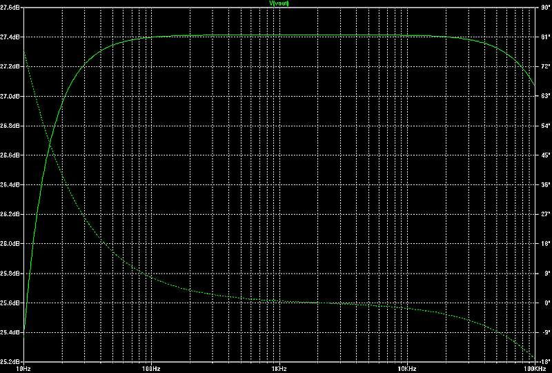
Just so I don't look like a total fool (yet again) I took the trouble to sim the poster's circuit in LTSpice. I guess I must have been thinking of something else in my previous suggestions.
I left in a 300 ohm grid stopper since it was there from a previous project.. anyway as expected the frequency response is as flat as can be with 100k Ohm load.
I hope the original poster will explain how they made their measurements.
Ian
Attachments

OK Soulmarchant
So now, have a look at higher frequency : you should see a - 3dB corner frequency around 1.3 MHz.
Add 600 pF in // with RG=220 k, the corner frequency drops to 8 kHz.
But the potentiometer at the input also reduce the bandwith when cursor not at the max position.
The Miller effect of the 12AX7 on its grid is Cpg(1+G) = 2.4pf(1+49) =120pF
When cursor is in the middle, equivalent source resistance is 25k//25k=12.5k, forming a low pass filter with a corner frequency at 1/(6.28x12.5kx120p) ~106 kHz ( with no 600 pF at the plate).
Of course, exact result from simulation depends on how your model includes parasistics capacitances of the tube.
Jacques, the Ayumi spice model I use includes values for parasitic capacitances and strays.
Let's look at your volume control idea. First of all, I think you underestimate the strays. I make the each 1pF just to be on the safe side.
For example, a typical 12AX7 stage has the following capacitances and gain:
Cgk = 1.6pF + 1.0pF stray = 2.6pF
Cgp = 1.7pF + 1.0pF stray = 2.7pF
A = 49 (we agree on this!)
Therefore, the total input capacitance would be:
Cin = 2.6pF + (49+1)* 2.7pF = 137.6pF
So then for full 50k lets calculate the 3db cutoff frequency:
f = 1/(2*pi*50K*137.6pF) = 23kHz
Lets wind the volume down to 1k such as in my attached simulation.
f = 1/(2*pi*1K*137.6pF) = 116Khz
So it looks like lower volume level should push up the 3db cut-off, doesn't it?
One possible explanation would be incorrect wiring of the volume potentiometer. I think many of us have done that one in the past. 😉
I don't understand your 600pF statement.. are you thinking of some cable effect? Please do explain if it is not too much trouble.
We still don't know how they did the measurement though....
Ian
Attachments

Last edited:
Hi Soulmarchant
Thanks for your comments
Yes I didn't take strays into account, because they are low compared with Miller effect
600 pF is the very high value of the capacitance needed to get a high corner frequence at 8 kHz, astornishing corner frequency stated by the original poster. Even with stray capacitances and 6V6 Miller effect, it is not possible to have so much capacitance at the plate as I said yesterday.
It was a suggestion for you to try this value in simulation and see the roll-off frequency.
Jacques
Thanks for your comments
Yes I didn't take strays into account, because they are low compared with Miller effect
correctFor example, a typical 12AX7 stage has the following capacitances and gain:
Cgk = 1.6pF + 1.0pF stray = 2.6pF
Cgp = 1.7pF + 1.0pF stray = 2.7pF
A = 49 (we agree on this!)
Therefore, the total input capacitance would be:
Cin = 2.6pF + (49+1)* 2.7pF = 137.6pF
Sorry, formula doesn't apply when cursor at full volume because resistance of the pot is in // and doesn't make any low pass filterSo then for full 50k lets calculate the 3db cutoff frequency:
f = 1/(2*pi*50K*137.6pF) = 23kHz
yes, because the lower part of the pot 1K is in // with the upper part of the pot (50-1=49k) # 1K (and source impedance =0)Lets wind the volume down to 1k such as in my attached simulation.
f = 1/(2*pi*1K*137.6pF) = 116Khz
I don't understand your 600pF statement.. are you thinking of some cable effect? Please do explain if it is not too much trouble.
600 pF is the very high value of the capacitance needed to get a high corner frequence at 8 kHz, astornishing corner frequency stated by the original poster. Even with stray capacitances and 6V6 Miller effect, it is not possible to have so much capacitance at the plate as I said yesterday.
It was a suggestion for you to try this value in simulation and see the roll-off frequency.
Jacques
Even with stray capacitances and 6V6 Miller effect, it is not possible to have so much capacitance at the plate as I said yesterday.
Yes, it is. Question 1 is still floating out there.
Where did OP go? (crickets chirping)
Anyway there are too many unknowns here about the testing method and equipment. Maybe the cathode bypass cap is bad or has a bad connection further raising output impedance, now combine that with the test equipment input capacitance and anywhere near 300pF will yield said results. 30pF/Ft x 10ft isn't unheard of.
Or if the 6V6 is triode wired wouldn't the input capacitance be in parallel with the test equipment's input capacitance which then could sum to a high value, possibly 600pF? He did say he bypassed the 6V6, I am not too sure what that means.
What is measured gain of the stage into the 220k load? If it's ~45 then the cathode is bypassed. Unbypassed will be ~18.
Sorry, formula doesn't apply when cursor at full volume because resistance of the pot is in // and doesn't make any low pass filter
Ahhh... do you mean to say miller capacitance is not a concern for 12ax7 MM phono amplifiers with nominal 47k Ohm input impedance?
Please feel free to elaborate. I am curious to hear your answer. 🙂
also.. hope the original poster will come around. Maybe he is now simply happy with 12au7 though. Sometimes a quick-fix is all that is needed.
Last edited:
Ahhh... do you mean to say miller capacitance is not a concern for 12ax7 MM phono amplifiers with nominal 47k Ohm input impedance?
yes, because the lower part of the pot 1K is in // with the upper part of the pot (50-1=49k) # 1K (and source impedance =0)
I don't want to answer for him but I believe he is talking about your simulation where the source isn't a MM cartridge.
Again nobody knows how to answer OP's original question because there is no reference of testing and exact equipment.
Ahhh... do you mean to say miller capacitance is not a concern for 12ax7 MM phono amplifiers with nominal 47k Ohm input impedance?
Please feel free to elaborate. I am curious to hear your answer. 🙂
No, calculated Miller capacitance is correct.
But when cursor of the pot is at max the serial resistance making a low pass filter is the output resistance of the sourcing device.
In your sim, this resistance is 0 beause you use a perfect voltage generator
In the case of a phono amplifier, the source, a moving magnet, has an internal resistance between 500 and 1500 ohm according to cartridge used ( much lower for a moving coil cartridge).
The input resistance of a phono amplifier ( 47 k as you said for a moving magnet ) doesn't make a low pass filter with the Miller capacitance produced by the 12ax7 at its grid.
I am affraid you are confused with output resistance (impedance) and input resistance (impedance).
Jacques
Not sure if this will add any value.
I've simulated and mesured the Quad 22 ECC83 output stage without the tone controls and the frequency response is 10hz – 100kHz into an amp with 680k grid resistor. I did try different amplifiers with values from 10K up to 1.5M, with the low values of resistance (10k - 200k) I loss the LF response and distortion increase, the HF response remained the same.

I've simulated and mesured the Quad 22 ECC83 output stage without the tone controls and the frequency response is 10hz – 100kHz into an amp with 680k grid resistor. I did try different amplifiers with values from 10K up to 1.5M, with the low values of resistance (10k - 200k) I loss the LF response and distortion increase, the HF response remained the same.
- Status
- Not open for further replies.
- Home
- Amplifiers
- Tubes / Valves
- Simple 12AX7 gain stage loss of HF - impedance?