Switches are correct.
1 and 2 on for Spdif. Oterwise no noise.
Swiches 3 and 4, to select 16 or 24 bit, I think are intended as ADC use. Makes no difference.
1 and 2 on for Spdif. Oterwise no noise.
Swiches 3 and 4, to select 16 or 24 bit, I think are intended as ADC use. Makes no difference.
Do you know how to check that the PCM I2S bus and MCLK signals are correct going into PCM2DSD using the scope? That DSD_ON is correct?
Then do you know how to check the DSD or PCM signals coming out of PCM2DSD with the scope?
Then do you know how to check the DSD or PCM signals coming out of PCM2DSD with the scope?
Allright my silly first think of the day, all readings were ground inverted. Thanks advice Markw4. File downloaded.
Here is MCLK better looking🙁afrer press " auto" button)

Here is MCLK better looking🙁afrer press " auto" button)
Okay. Each square wave cycle is about 3 horizontal divisions long on the scope. Also, looks like the scope is set to 1 us/division? If so, one cycle of the square wave takes about 3 us, which is its period.
Frequency = 1/period, so the frequency is 1/3us = 333kHz. That can't be MCLK, at least its not a valid MCLK for an Amanero. It has to be around 22MHz or 24MHz only.
Frequency = 1/period, so the frequency is 1/3us = 333kHz. That can't be MCLK, at least its not a valid MCLK for an Amanero. It has to be around 22MHz or 24MHz only.
I dont know how to check neither PCM or DSD.
I post here just in the hope I got any silly pin miswiring in order to connect DSD2PCM out of their as designed environtment. Now is deceiving, I realise my wiring is correct.
I preciate the help, but feel unconfortable here.
My best move is acquiring the Spdif receiver module form Ian canada, to match their fifo I already have.
I Stored a FifoPiQ7 board with expensive 22.xxx 24.xxx clocks for this PCM2DSD project, so makes sense complement it with their flagship receiver (isolated spdif input).
Last edited:
Its isn't just that your wiring has to be correct. What has to be correct is also the signal formats, including I2S bus, MCLK, DSD_ON, and MUTE. If any one of them is wrong, then it won't work. There is more than one standard for those signals, so you need to know which standard you need to follow. If you can't measure, then you can't be sure why it isn't working.
Your best bet might be to buy an ASRC board, such as an AK4137 board, which can convert your SPDIF receiver output to a format the PCM2DSD can accept. There used to be some AK4137 boards with a AK4118 SPDIF receiver on the same board. Don't know if they still make those or not. However, you would have to make sure the AK4137 board uses the right master clock frequencies that you need
A FIFO board could work too, so long as it accepts the input format the SPDIF board is outputting, including the particular inversion of DSD_ON. Otherwise you may need to make your own inverter, if one is needed.
Last edited:
This spdif module not have DSD pin in the output interface, see atch.
I see Mclk output without a matching ground. It is a concern ?
Don't know if worth the hassle trying to connect to the fifoPiQ7II.
Which is another nightmare. I don't see anywhere a Mclk "input" shocket
Will work PCMm2DSD module without Dsd-on input?
All in all, I don't need dsd feature.
.

I see Mclk output without a matching ground. It is a concern ?
Don't know if worth the hassle trying to connect to the fifoPiQ7II.
Which is another nightmare. I don't see anywhere a Mclk "input" shocket
Will work PCMm2DSD module without Dsd-on input?
All in all, I don't need dsd feature.
.
Don't know if FIFO_Pi will support the sample rate or not, and even if it does then PCM2DSD may not support it. In either of those cases, an ASRC is probably the best solution. Unfortunately, the old AK4137 boards with 22/24MHz master clocks appear to be no longer made. However, looks like I have one in my junk box:

It uses 22/24MHz clocks, and IIRC, an option to export the MCLK signal. It has TOSLINK and SPDIF inputs, and also a place to plug in an Amanero USB board. I think it should be workable with your PCM2DSD board, but that's just my guess from memory. If you want you can have it, but you would have to pay for shipping, and you would have to wait until after the holidays before I am going to the post office again.
All the above having been said, I would not use this as is myself. The clocks and clock power supply are poor, the MCU creates digital noise on the power rails that affects the ASRC quality, etc. Its definitely compromised in terms of actual SQ versus what AK4137 is capable of under better conditions, which is why its in my junk box.
Last edited:
I want it, I'll contact PM, thanks!
Amanero shoket should accept my Singxer F-1 module as well. Does an Xmos interface is compatible with PCM2DSD module?
Amanero shoket should accept my Singxer F-1 module as well. Does an Xmos interface is compatible with PCM2DSD module?
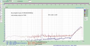
The PCM2DSD file has been updated to support DSD256. It uses a 4th-order 1-bit DSM. Since the OSR is higher, local feedback (g0 and g1) is unnecessary and would be difficult to implement given the FPGA's capacity. The gain is set so that 0 dBFS in PCM corresponds to -6 dBFS in DSM. Most DACs account for this by adding a 6 dB gain to DSD, resulting in the same output level as PCM. For example, with the D90 (AK4499EQ) used for measurement, 0 dBFS in PCM equals 4 Vrms and -6 dBFS in DSD also equals 4 Vrms. Thus, 0 dBFS (PCM) = -6 dBFS (DSD) = 4 Vrms.
Details of the results:
Pic.2: This shows the measured digital and analog values for a 1 kHz signal. The digital SNR is slightly degraded due to calculation precision, but it should ideally be around 140 dB.
Pic.4: Displays out-of-band noise. Many discrete DACs use a 16-tap FIR filter, so the characteristics should be similar.
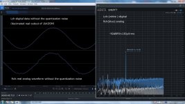
Pic.5: Shows a small signal output at -90 dBFS, the same level as the minimum output of a CD. The analog output closely matches the digital input (DSD256), demonstrating the excellent performance of the AK4499 in handling DSD. After removing quantization noise, the result is as shown in Pic.6, which more accurately reflects the real-world performance.
Instabilities and mitigation:
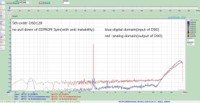
For a 1-bit DSM, the output can become slightly unstable when the input signal level drops (around -60 dBFS), leading to increased distortion and fluctuating quantization noise. For example, as shown in Pic.7 and 8, the Rch exhibits periodic fluctuations every three seconds. This instability is inherent to the modulation method and order, and each system will have its characteristics. Various techniques can be used to suppress this.
In the Lch example, "anti-instability" is implemented by superimposing a carrier signal at around -30 dBFS with a frequency of approximately (1/16)fs. In the case of DSD256, this corresponds to a signal at about 700 kHz, which does not appear in the analog domain (Pic.4) as the analog FIR filter removes it. This carrier stabilizes the quantization noise but introduces sideband-like distortion at around -150 dBFS (Pic.9). While this does not affect the analog domain in the D90, it may have an impact in some cases.
Optional adjustment:
To disable this effect, pull down the 5-pin of the EEPROM with a resistor of approximately 3.3kΩ. When disabled, the results are as shown in Pic.10(no superimposing). The choice between enabling or disabling this feature depends on the specific environment and application.
Details of the results:
Pic.2: This shows the measured digital and analog values for a 1 kHz signal. The digital SNR is slightly degraded due to calculation precision, but it should ideally be around 140 dB.
Pic.4: Displays out-of-band noise. Many discrete DACs use a 16-tap FIR filter, so the characteristics should be similar.
Pic.5: Shows a small signal output at -90 dBFS, the same level as the minimum output of a CD. The analog output closely matches the digital input (DSD256), demonstrating the excellent performance of the AK4499 in handling DSD. After removing quantization noise, the result is as shown in Pic.6, which more accurately reflects the real-world performance.
Instabilities and mitigation:
For a 1-bit DSM, the output can become slightly unstable when the input signal level drops (around -60 dBFS), leading to increased distortion and fluctuating quantization noise. For example, as shown in Pic.7 and 8, the Rch exhibits periodic fluctuations every three seconds. This instability is inherent to the modulation method and order, and each system will have its characteristics. Various techniques can be used to suppress this.
In the Lch example, "anti-instability" is implemented by superimposing a carrier signal at around -30 dBFS with a frequency of approximately (1/16)fs. In the case of DSD256, this corresponds to a signal at about 700 kHz, which does not appear in the analog domain (Pic.4) as the analog FIR filter removes it. This carrier stabilizes the quantization noise but introduces sideband-like distortion at around -150 dBFS (Pic.9). While this does not affect the analog domain in the D90, it may have an impact in some cases.
Optional adjustment:
To disable this effect, pull down the 5-pin of the EEPROM with a resistor of approximately 3.3kΩ. When disabled, the results are as shown in Pic.10(no superimposing). The choice between enabling or disabling this feature depends on the specific environment and application.
Attachments
-
 pic10_4th_without anti.jpg270.5 KB · Views: 63
 -
 pic9_4th_with anti.jpg270.1 KB · Views: 57
 -
 pic8_4th_instability2.jpg294.1 KB · Views: 58
 -
 pic7_4th_instability1.jpg289.8 KB · Views: 52
 -
 pic6_4th_-90dB_LPF.jpg292.9 KB · Views: 55
 -
 pic5_4th_-90dB.jpg343.1 KB · Views: 59
 -
 pic4_4th_1M_FFT.jpg163.5 KB · Views: 56
 -
 pic3_4th_32tone_cmp.jpg365.1 KB · Views: 50
 -
 pic2_4th_1k_cmp.jpg283.1 KB · Views: 58
 -
pcm2dsd_x256.zip172.9 KB · Views: 50

Looks like a newer version than what I have. It can be improved by modifying it to run the AK4137 and the mux chip on clean power. Also, the clock power supply can be redone or else external clocks brought in. Each of those mods IME makes an audible improvement in SQ. However, I wasn't using the AK1118 so maybe it would help for it to be on clean power too. Biggest problems with the power is that the MCU puts a lot of noise on the +3.3v power rail, and the existing regulator isn't all that great either. Also, clocks have ferrites in their power supply which I prefer to avoid for clocks. Don't know of those clocks are NDK SDA but probably not. If you can solder small stuff like that then they can be replaced. If you decide to get the board and if you want to, I can tell you how to do the mods via PM so we don't clutter up this thread going forward....an ASRC board on sale in Aliexpress...
This is the DSD128 version of PCM2DSD. It uses a 5th-order 1-bit DSM with a single local feedback loop (g1) to shift more quantization noise out of the audio band. The gain setting is the same as DSD256, with 0 dBFS (PCM) = -6 dBFS (DSD). The oversampling is also 706 kHz and an additional moving average filter.
Pic.2 shows the characteristics of a 1 kHz signal. Due to residual ADC noise (approximately -127 dBFS), the actual SNR is around 120 dB, which is, to my knowledge, the highest value achieved with a 1-bit DSM. It significantly outperforms designs like Chord's. This configuration should have better numerical results for discrete DAC applications than DSD256.
Pic.3 shows the oversampling characteristics. The gain here is -6 dB, so overflow will not occur with any CD input. However, for a 5th-order DSM, the maximum stable amplitude is approximately -5 dBFS, which can cause overflow due to this limitation. A 4th-order DSM is slightly more advantageous, with a maximum stable amplitude of about -4 dBFS. The AK4499EQ seems to slightly reduce the gain of its internal oversampling filter, clipping at around +2 dBFS based on measurements. This provides a robustness comparable to a 4th-order 1-bit DSM in practical use. While this figure isn’t documented in the datasheet, it gives a considerable advantage when playing CDs, even with I2S input.
Pic.4 shows the out-of-band noise. Since the OSR is lower, the spacing between the peaks of the noise-shaping notches becomes narrower. Pic.5 and Pic.6 show the characteristics at -90 dBFS. The quantization noise is higher than with a 4th-order DSM, so without an LPF, the waveform does not resemble a sine wave. However, compared to SACD with DSD64, the quantization noise is dramatically lower. For SACD, the sine wave shape disappears at around -40 dBFS. The waveform becomes clean when passed through an LPF (Pic.6).
Pic.7 and pic8 illustrate stability at low-level output (-60 dBFS). As with the 4th-order DSM, the quantization noise fluctuates. For the 5th-order DSM, the fluctuation period was approximately five seconds. Adding a correction stops this fluctuation. Similar to the 4th-order DSM, sideband-like distortion appears but does not affect the analog domain in the D90.
Pic9 and pic10 compare the 4th- and 5th-order DSMs. With a lower OSR, the SNR is better for the 5th-order DSM, while quantization noise is lower with the 4th-order DSM. In both cases, the DSD performance of the AK4499EQ is exceptional. Achieving these figures with a discrete DAC would be highly challenging.
Attachments
-
pcm2dsd_x128.zip202.7 KB · Views: 47
-
 pic2_5th_1k_cmp.jpg281.1 KB · Views: 50
 -
 pic3_oversampling.jpg196.7 KB · Views: 50
 -
 pic4_5th_1M_FFT.jpg186.9 KB · Views: 51
 -
 pic5_5th_-90dBFS.jpg340.7 KB · Views: 45
 -
 pic6_5th_-90dBFS_LPF.jpg295 KB · Views: 43
 -
 pic7_5th_with.jpg264.5 KB · Views: 48
 -
 pic8_5th_without.jpg264.7 KB · Views: 50
 -
 pic9_DSD_4th_5th_0dBFS.jpg269.7 KB · Views: 44
 -
 pic10_DSD_4th_5th_-40dB.jpg246.1 KB · Views: 50
Hi all ... I have been following this interesting thread on & off for some time now and this morning have been reading some way into the thread trying to find some information about the latency - or delay - of this circuitry but not really finding it? Since I also use my DAC for a digital piano the delay matters in this context ...
Thanks for any info on this 😉
Jesper
Thanks for any info on this 😉
Jesper
Perhaps interesting, the new 1-bit "Topping D90 III Discrete" dac is claimed to have 130dB DNR and 131dB SNR....the actual SNR is around 120 dB...
https://www.toppingaudio.com/product-item/d90-iii-discrete
According to one review it is said to sound pretty good too:
https://soundnews.net/reviews/sources/topping-d90-iii-discrete-review-our-favorite-dac-under-1000/
Pics of PCB at:
https://www.headfonia.com/wp-content/uploads/2024/12/topping-d90-iii-discrete-pcb3.jpg
https://www.headfonia.com/wp-content/uploads/2024/12/topping-d90-iii-discrete-pcb2.jpg
Last edited:
Hi again ... with reference to post #1095 just above I would like to add that I will now be off on a short Christmas vacation so I will not reply to the thread in a week's time. However, if someone knows about the latency of the PCM2DSD board I would appreciate hearing about it (will read it later on) as it will be a decision parameter for me.
Cheers & Merry Christmas to everyone 😉
Jesper
Cheers & Merry Christmas to everyone 😉
Jesper
Don’t forget to add A-weighted. 120dB(A) is trivial to get. 130 is only 3 times better. But who really needs that?"Topping D90 III Discrete" dac is claimed to have 130dB DNR and 131dB SNR.
Best guess would be Topping really needs it. It costs a lot, so some folks will expect it to measure accordingly. Maybe there are some compromises Topping used to hit the target performance and pricing numbers? For example, a clock can be seen in one pic of the FIRDAC dac daughterboard. One clock. So how does it handle USB? ASRC?
Last edited:
- Home
- Source & Line
- Digital Line Level
- Simple DSD modulator for DSC2