IMHO, if you insert an output transformer or autoformer of some sort, it's not anymore... An OTL amplifier ! 😉
A single 6AS7 or 6080 in a patent-Futterman circuit would put 1W RMS on 16R load. The Audio circuit would be quite simple, but unfortunately not the supply, which requires : one symetrical HV voltage for the 6080, one HV voltage for the preamp section, one negative voltage for the bias of the lower 6080... 😕
T
Last edited:
Yes, that's right for sure. But it helps to increase efficiency and decrease investment, if a cheap mains toroid would work (which has to be proven yet...).
Best regards!
Best regards!

Yes, that's right for sure. But it helps to increase efficiency and decrease investment, if a cheap mains toroid would work (which has to be proven yet...).
Best regards!
Well, I'd say that if you are in search of some efficiency for moderate investment... IMHO, rather forget the OTL amps circuits ! I mean those without any output transformers, otherwise the main benefit of the elimination of the said transformer is lost.
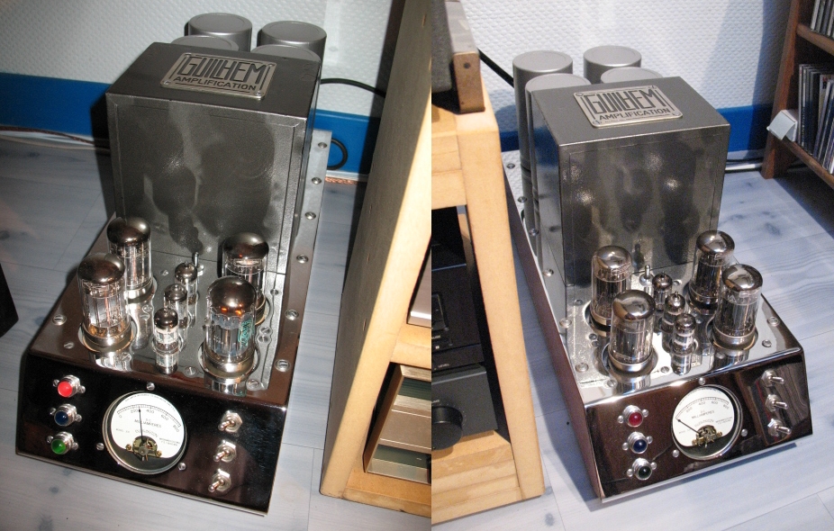
Let's just check the datas for my U-OTL6080 :
1 - For 10WRMS output, the pair of mono blocks draws 1.8A on 230VAC, that is to say 1.8*230=414W.
2 -They deliver 10WRMS per channel, so let's calculate the total level of efficiency : (10+10)/414=4.83% ! 😱Properly unefficient, I must confess... 😕
Oh, it's me, or it seems that we are very far from... Some class D operation amp ? 🤣😉
T
This was about a simple OTL amplifier 🙂
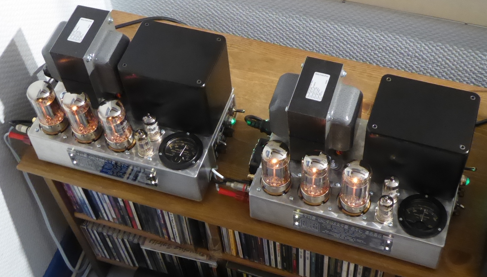
I added some pictures to my thread in post 9, to show I actually built that amp 🙂 I think it quite simple, tubes and sockets are a bit exotic, therefore I would recommend 6C45P now, they would make more power than the 17KV6, but they can be run conservatively and will then probably last a lifetime.
I replied to this thread because the author already noticed that a higher impedance (series connected speakers) makes sense with OTL. I only did mine because I too have the possibility for series connection fo the speakers, and therefore higher impedance, and while I know that 5W is indeed more than enough. I use the 17KV6, it's heater is about 10W and I keep it biased at circa 10W, so all four dissipate 80W. I do have some 6C33C, only the heater of four of these already dissipate 140W. With the pentode connected 17KV6, I can also swing more volts at the plate compared to the 6C33C: generally tubes are current limited, but at certain moment with higher impedance loads, the plate swing starts to play a role as well (experienced that in another OTL I am building, with parallel connected 22JF6.
Anyway, to test the OTL sound, I am happy I was able to put the 17KV6 to use to get the 10W into 72R with circa 80W heat. I would not do the same with 6C33Cs. And I can only recommend one to try it out. Not for free, but not terribly expensive either. Isolation transformers for the power supply, SMPS for heaters are actually cheaper than new linear power transformers...
The Futtermann could be made to be a current amplifier, I must have some sketches somewhere, if I find them I will post them.
Much of this thread is not about OTL amplifiers.
Instead, it is about wiring multiple drivers in series, in order to make them into "a more friendly load" for the OTL amplifier.
I think that wiring drivers in series has many design considerations and tradeoffs.
driver DCR versus driver total impedance versus frequency
driver mechanical Q
driver's enclosure: closed, open, ported, transmission line, horn, etc.
and other factors.
Before designing a playback system that includes an OTL amplifier . . .
I suggest starting a thread in the various classes of loudspeakers.
Ask the experts for advice about wiring drivers in series,
and what are the design ideas to make the loudspeaker work well with an OTL amplifier.
The original thread should include the expected ratio of the series wired driver's total loudspeaker impedance, versus the OTL impedance.
Just my opinions
Simple?
https://audioxpress.com/article/your-can-diy-a-25w-otl-tube-amplifier
https://www.bonavolta.ch/hobby/en/audio/6336a_1.htm
https://web.archive.org/web/20100202221135/http://www.tubebuilder.com/schematic3.html
https://diyaudioprojects.com/mirror/members.aol.com/sbench101/
only 2 watts
https://diyaudioprojects.com/mirror/members.aol.com/sbench102/PowerAmps/se_otl.gif
page 13
https://www.worldradiohistory.com/Archive-All-Audio/Archive-Audio/50s/Audio-1955-Jul.pdf
-----
12b4a 6s4a 6au6 6bq7a
Last edited:
Gold mine of DI¥ audio tubes schematics from Japan
search OTL this threadhttps://www.diyaudio.com/community/threads/gold-mine-of-di-audio-tubes-schematics-from-japan.311212/
That last Sansui OTL schematic: V5 - V112 😳 Are there any 12B4s left?
There are numerous modern bipolar power transistors around that have a constant Beta (current gain) parameter. Put such NPN and PNP power transistors under or over the output tubes (like a Darlington) to increase the current efficiency, but preserve the tube sound. In any case, the tubes will sound better if they are not overloaded anyway. Especially triodes.
There are numerous modern bipolar power transistors around that have a constant Beta (current gain) parameter. Put such NPN and PNP power transistors under or over the output tubes (like a Darlington) to increase the current efficiency, but preserve the tube sound. In any case, the tubes will sound better if they are not overloaded anyway. Especially triodes.
from post #66
The 6337 tube looks extinct
page 13
https://www.worldradiohistory.com/Archive-All-Audio/Archive-Audio/50s/Audio-1955-Jul.pdf
-------
Bona
https://www.bonavolta.ch/hobby/en/audio/audioel.htm#Amps
--
Andrea Ciuffoli- Audiodesignguide
https://www.audiodesignguide.com/myamp.html
The 6337 tube looks extinct
page 13
https://www.worldradiohistory.com/Archive-All-Audio/Archive-Audio/50s/Audio-1955-Jul.pdf
-------
Bona
https://www.bonavolta.ch/hobby/en/audio/audioel.htm#Amps
--
Andrea Ciuffoli- Audiodesignguide
https://www.audiodesignguide.com/myamp.html
Last edited:
Much of this thread is not about OTL amplifiers.
Instead, it is about wiring multiple drivers in series, in order to make them into "a more friendly load" for the OTL amplifier.
I think that wiring drivers in series has many design considerations and tradeoffs.
driver DCR versus driver total impedance versus frequency
driver mechanical Q
driver's enclosure: closed, open, ported, transmission line, horn, etc.
and other factors.
Before designing a playback system that includes an OTL amplifier . . .
I suggest starting a thread in the various classes of loudspeakers.
Ask the experts for advice about wiring drivers in series,
and what are the design ideas to make the loudspeaker work well with an OTL amplifier.
The original thread should include the expected ratio of the series wired driver's total loudspeaker impedance, versus the OTL impedance.
Just my opinions
Indeed, one could feed the series connected speakers from an existing amplifier and see what it sounds like. An amplifier that can deliver 100W in 8R has an output of 28V RMS, which will be about 10W into 72R. With this simple exercise, the author can check how it sounds, even compare an existing current amplifier with a voltage amplifier to see how all that additional added RDC impacts the performance.
In my man's cave I have an open baffle speaker with 8x 4 ohm (sub)woofers. I once wired these in series, for 32R, and fed from a current amplifier: I soon realized what Fs is all about, it was terrible. Then I fed the 32R from a voltage amplifier, it was not as bad as the current amplifier, but clearly not good either around Fs. Then I took a pair of speakers and wired them in parallel, so I had 4 pairs of 2R each. These I then connected in series, for 8R. This works the best, probably because individual speakers are fed from relatively low DCR. Unfortunately, not a good match for OTLs anymore.
The same speaker has 32 4R fullrange units. These are divided in 4 groups of 8 speakers connected in series, so 4x 32R. These can be connected all in series (128R load), two in series, then two parallel (32R), or all in parallel, for 8R. When I played all in series from a current amplifier I thought: much better highs, wow, what a difference, only to later realize that the highs were tiring and that they were being played louder because the impedance rises at higher frequency, so they were getting more power at higher frequency. No problem around Fs though, as FS is about 100Hz and they have a LR HP filter at circa 500Hz.
I took a look at the other work by @Freedom666 and most of it concerns speakers, so in my opinion, I think he has his experience there and could be well served with an actual discussion around an actual "Simple OTL for beginners" as requested.
Last edited:
If the 6AS7 can make 1W into 16R, it will make about 5W into 80R. For that, it must swing 20V RMS into 80R, or 60Vpp. So you could have about 5W into 72R by using one tube per channel. 6AS7 is widely available, low cost, uses a common octal socket, no topcap, nice looking, what is not to like? 🙂IMHO, if you insert an output transformer or autoformer of some sort, it's not anymore... An OTL amplifier ! 😉
A single 6AS7 or 6080 in a patent-Futterman circuit would put 1W RMS on 16R load. The Audio circuit would be quite simple, but unfortunately not the supply, which requires : one symetrical HV voltage for the 6080, one HV voltage for the preamp section, one negative voltage for the bias of the lower 6080... 😕
T
Thinking about simplicity and available parts, I would use a PT with dual secondaries of 115V, which gives +-150V combined with the tubes in auto bias. Looking at the curves, about 110V from plate to cathode, and another 40V in the cathode resistor (500R). This gives about 80mA current (red circle on the diagram). The loadline is not exactly 80R, but close, it looks like the tube will be able to do 60Vpp. This will have a lot of heat in the resistor, but so much simpler to build and better long term stability.
I got some inspiration for my builds from this thread
https://www.diyaudio.com/community/...s-approval-otl-autobias-inv-futterman.182181/
He uses the inverted Futterman, which requires more stages in order to keep the phase right for NFB. I use the normal Futterman (non inverting) and found out that a gyrator loaded pentode gives a lot of gain that I use for a of NFB to bring down distortion.
Thinking about it, I may actually try it out, as it is even simpler (no G2 supply to care about) than the OTL I presented in post 9.
Best regards,
Erik
Attachments


Please note that the 6336 is a very much beefier tube than 6AS7G and it's derivatives. I guess you need twice the tubes count to achieve the same performance.
Best regards!
Best regards!
Thanks to all until now.
I need some time to read the threads which were proposed.
I can only ever do an amplifier if everything is written and well readable like for a beginner.
Cs without voltage for example - then I do not know which to use. In a 300v amp then any C must have 400v then?
Where do I have to use foils if it's better or just normal electrolytic?
Freedom666
You can also check Audioxpress magazine from 05-2014 , there you can find pretty well described how to DIY Julius Futterman very early small OTL amp from 1954 ,
whole article is pretty good except for one small but important mistake in the schematic.
You can also check Audioxpress magazine from 05-2014 , there you can find pretty well described how to DIY Julius Futterman very early small OTL amp from 1954 ,
whole article is pretty good except for one small but important mistake in the schematic.
Attachments

1. In the early 1970s, a very well controlled double blindfold listening test was conducted.
The results were published in a major audio magazine.
A number of solid state amplifiers were compared to each other, and to a Futterman amplifier.
Statistically, there was not a detectable or repeatable difference between the sound of those amplifiers.
Many criticisms have existed about those test results, because the results do Not Appeal to many audio fans.
OK.
But here is what I find most interesting about that listening test . . .
All of those amplifiers, solid state, And Futterman have 2 characteristics in common:
A Totem Pole output stage (serial output transistors, and serial tubes).
And
Very Large amounts of global negative feeback.
You can raw your own conclusions.
I have drawn my conclusions.
2. There are people who believe that properly conducted double blindfold listening tests can settle lots of differing opinions.
I ran two completely different double blindfold listening tests:
One was very successful; 3 venues, 3 different audiences, al same results.
The other one, at VSAC 2008, was pretty good. But when I ran it, I discovered a flaw in the test setup. I figured out how to fix that, but I never went to the trouble to run the listening test again (including finding such a good venue, and a good set of listeners).
Just my opinions
If the 6AS7 can make 1W into 16R, it will make about 5W into 80R. For that, it must swing 20V RMS into 80R, or 60Vpp. So you could have about 5W into 72R by using one tube per channel. 6AS7 is widely available, low cost, uses a common octal socket, no topcap, nice looking, what is not to like? 🙂
Easy : 10 speakers at 8 ohms, so 20 speakers total in stereo ! I do not consider this a simple solution vs. a fixed bias operation of a single 6080... Plus it's not versatile : these 72R speakers or nothing.
I built in 1983 my first OTL with one 6080, using decoupled cathode bias. It proved to be a poor idea, and I shifted to fixed bias quickly : distortion, bandwidth and power output were significantly improved. In fact, the cathode bias operation - but with un-decoupled cathode resistors - worked as fine as the fixed bias operation, but the drawback was that the power output was correct for... An headphone amp.
With a decoupled cathode bias operation - even with 3300µF - a 6AS7 or a 6080 in OTL circuit won't be able to offer the square waves as I displayed in my post #56, unless you apply a high level of NFB :
https://www.diyaudio.com/community/threads/simple-otl-for-beginners.407554/post-7566933
Nonetheless, yes : 10 speakers in serie par channel, that's perfectly doable, but what is not in the amp is compensated by the number of speakers : not more simple and rigid solution, IMHO - not for me, at least !
But it's me, OK ? 😉
T
Last edited:
here`s corrected schematic , negative bias source for lower bank of power tubes have not to be referenced to ground line which is dangerous but to -157V line .Freedom666
...whole article is pretty good except for one small but important mistake in the schematic.
Attachments

As old Radio&TV repairman I have repaired so many different mass produced solid state amps ,where majority of them sounded lifeless(like sh..t) to me and far far away from the real music , on the other side way so many good designed conventional tube amps sounded just OK to me inclusive with some DIY Futterman OTL amps ,and Atmasphere based OTL amps, tube amps are simply another world of amplification compared to solid state amps ,1. In the early 1970s, a very well controlled double blindfold listening test was conducted.
The results were published in a major audio magazine.
A number of solid state amplifiers were compared to each other, and to a Futterman amplifier.
Statistically, there was not a detectable or repeatable difference between the sound of those amplifiers.
Many criticisms have existed about those test results, because the results do Not Appeal to many audio fans.
OK.
But here is what I find most interesting about that listening test . . .
All of those amplifiers, solid state, And Futterman have 2 characteristics in common:
A Totem Pole output stage (serial output transistors, and serial tubes).
And
Very Large amounts of global negative feeback.
You can raw your own conclusions.
I have drawn my conclusions.
2. There are people who believe that properly conducted double blindfold listening tests can settle lots of differing opinions.
I ran two completely different double blindfold listening tests:
One was very successful; 3 venues, 3 different audiences, al same results.
The other one, at VSAC 2008, was pretty good. But when I ran it, I discovered a flaw in the test setup. I figured out how to fix that, but I never went to the trouble to run the listening test again (including finding such a good venue, and a good set of listeners).
Just my opinions
but admit , there`s allways some rare exception even for solid state amps , where couple of A class CFA amps , and couple of AB class
Singleton amps sounded just very acceptable to me .
Last edited:
This will have a lot of heat in the resistor, but so much simpler to build and better long term stability.
I'm not sure that 2 quite big caps 3300µF/63V plus a duet of heating resistor is much better about simplicity - and moreover - reliability than a fixed bias operation OTL, in this particular case.
I built those 20W OTL with 4x6080 / 20WRMS fixed bias (below) in 1996, I sold them in the mid-2000 to a friend who still owns them without issue since then, if we except a set of new tubes :
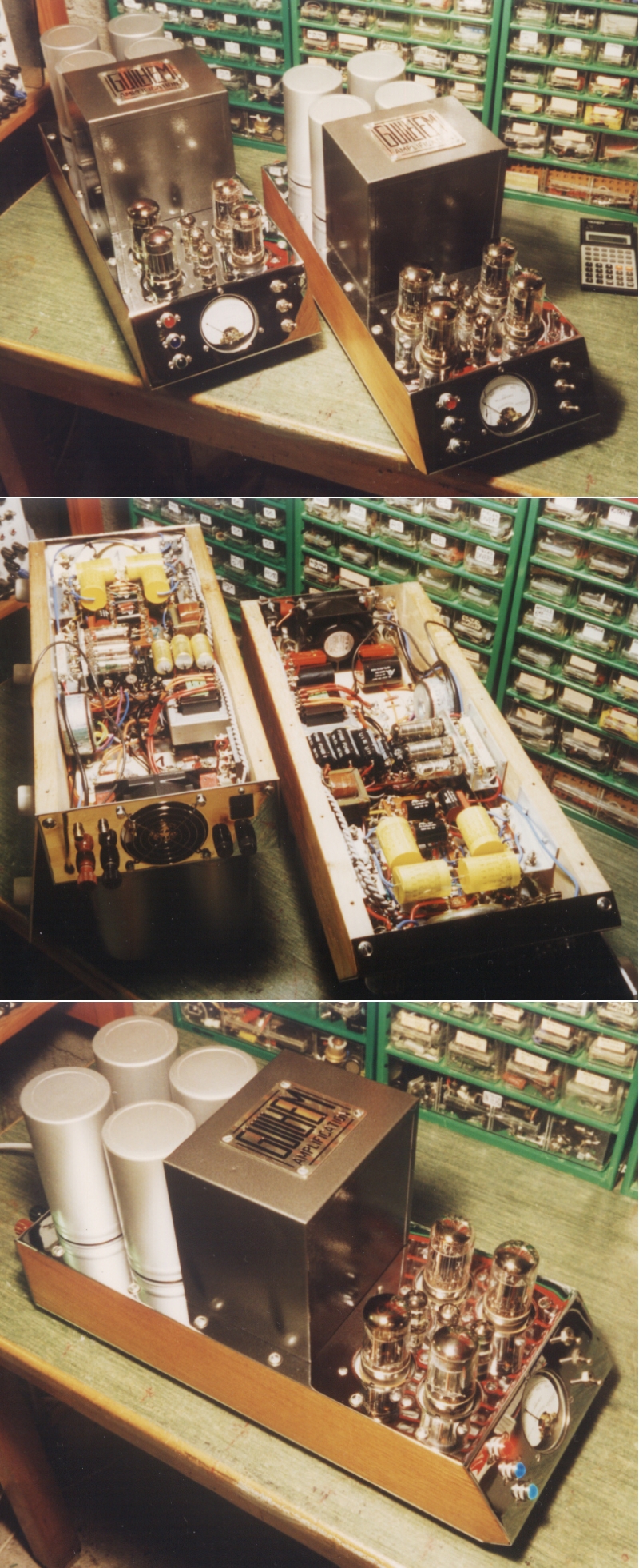
I sold them because... They were heavy and big ! 🙄 But that's nonetheless true, compared to the size of my U-OTL of today !
T
- Home
- Amplifiers
- Tubes / Valves
- Simple OTL for beginners?