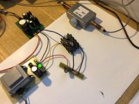
@lineup, we can build a good amplifier (and not only show the simulations). Again, the goal was to build the simplest possible, however usable amplifier. There are dozens of threads with more complex circuit structures, but they are off topic here.
This is the real class A amplifier with THD < 0.0001%
https://www.diyaudio.com/community/threads/small-class-a-amplifier-with-thd-below-0-0001.385676/
But again, in this thread are such creations off topic.
This is the real class A amplifier with THD < 0.0001%
https://www.diyaudio.com/community/threads/small-class-a-amplifier-with-thd-below-0-0001.385676/
But again, in this thread are such creations off topic.
Last edited:
Hello PMA,
Is it much to ask for the basic calculations of component values of your original circuit?
Is it much to ask for the basic calculations of component values of your original circuit?
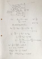
No, it is fine and the basic calculation has been already posted as equations in post #1. I also posted more equations in another thread, so I am posting it here as well. Please change resistor numbers according to post #1, it is really trivial. Also npn/pnp and polarity of capacitors and battery.Hello PMA,
Is it much to ask for the basic calculations of component values of your original circuit?

I have just built a second sample (we are always talking about #1 schematics) and it is crazy, the second Sanken 2SA1102 has Beta = 151 !! So the sample idle current was about 780 mA, too much, the emitter resistor temperature was going to high. So I increased the base biasing resistor from 1k to 1k8, now getting 600mA idle current. I will test it this way.
Of course it’s CHEATING. There are a lot of transistors inside that op amp.But again, in this thread are such creations off topic.
Just going to TWO transistors is cheating, but an easy solution to the lack of voltage gain. But if you are using a sound card or DAC, it will be capable of nearly 5V output. Less at 32 ohms, but with any decent transistor you can beat that by a factor of five. An old-school CD player that only puts out 200 mV might not cut the mustard. Does anybody still have one? I threw my old Sony out years ago when it quit reading most modern discs with the rootkits. Ones issued prior to all that garbage read fine. Modern pro units (ie Denon) can put out plenty of whallop out of the XLRs.
Would one of the Sanken darlingtons be considered cheating, since its really two transistors? No more voltage gain than a single, but would run at full output off a 50k source. Maybe somebody’s got a tube DAC…
Regarding CD players, all of them I have had since 1992 have had 2V approx. output rms voltage, with output resistance of 50 ohm - 680 ohm. Still, good to use regulated headphone output. The tape recorders I had before had had 300 - 500 mV line output, with quite high output impedance. That would be insufficient.
2V MAX output voltage at digital clipping, but nominally about 200 mV. Which plays at the right volume with loudness wars CDs when run into a unity gain buffer. With earlier recordings you’re lucky to get 20 mV typical signal level, which may be too quiet. At least if you have software you can move the range to what works best with your amp/speakers/desired level.
BTW, it takes a lot more than one transistor to make a DSP or DAC. Or even the output buffer in an old-school Soundblaster card.
BTW, it takes a lot more than one transistor to make a DSP or DAC. Or even the output buffer in an old-school Soundblaster card.
In such case, measurement on a real circuit is more valid than the simulated result. Think it over, if even in case of such a simple circuit there are some differences, how would it be in case of much more complex amplifier?? Do you still think that simulation models are accurate enough to tell you truth? Sometimes the result is too optimistic, sometimes a bit pesimistic. Simulation is only a first step in creating an amplifier project.I had to select more than 500mA bias to achieve 0.3Watt less than 1% THD
Not nominally, you mean average rms value of typical music signal. Rated output is 2Vrms for 0dBFS without any clipping. Anyway, standard output of 2V dBFS is able to drive 87dB/W/m speaker into normal desktop listening level and for the background listening it still has to be attenuated. I have it just beside me on my desktop 🙂. Still in one channel only.2V MAX output voltage at digital clipping, but nominally about 200 mV
When it’s 20 dB below full scale that’s probably about right. But 40 dB below isn’t loud enough. Maybe 50uW of power is enough for you, but not for me. Not with the AC/heat running, a desktop PC with 4 fans, and a snoring dog. It takes a few milliwatts (or tens of them) to overcome.
Here is my version of @PMA circuit.
I had to select more than 500mA bias to achieve 0.3Watt less than 1% THD.
In such case, measurement on a real circuit is more valid than the simulated result. Think it over, if even in case of such a simple circuit there are some differences, how would it be in case of much more complex amplifier?? Do you still think that simulation models are accurate enough to tell you truth? Sometimes the result is too optimistic, sometimes a bit pesimistic. Simulation is only a first step in creating an amplifier project.
This is a comparison of built samples of the Simplest amplifier. 2 different pieces of 2SA1102 transistors, btw, after investigation of case labelling, one of them (the one with low Beta) seems to be an unoriginal copy from who knows who producer. All the info is in the graph. And, this is not a simulation, this is the measurement!!
But 40 dB below isn’t loud enough. Maybe 50uW of power is enough for you, but not for me.
Of course it is not enough for me.
This is my main amplifier
https://pmacura.cz/DIY_250W_4ohm_amplifier.html
... and you may check my webpage
https://pmacura.cz/audiopage.html
to find > 2 x 300W/4ohm amplifier, small series of them sold 14 years ago.
But this project is for fun and for finding simplicity limits. It is not aimed for listening of philharmonic orchestra in full realistic level.
Please forgive me, I will not continue in such debate. I do not like a debate for the debate. If there are technical questions that would lead to some useful findings or ideas, then I am open.
Would be interesting to do simulation and see how it correspond to reality.
You say SPICE is sometimes is optimistic and other times pessemistic. And of course you are right.
You say SPICE is sometimes is optimistic and other times pessemistic. And of course you are right.
It's enough for me 🙂Of course it is not enough for me.
I use flea watt tube amps with the most simplistic tube circuit I could find, but the power consumption of the tube amps is still quite high (60W per stereo pair, using two is 120W) so that explains my interest if your great little amp sounds good. Running off a battery would be great for off-grid application. But you will need high efficiency speakers to have acceptable loudness levels.
Hi @Horneydude , yes it sounds good as long as it stays within its level limits, below 2Vrms output voltage. It needs capacitance multiplier as shown in post #1 to be supplied from smooth DC voltage. Then, there is absolutely no noise even with ear on the speaker. The sound is dynamic with good impact. As the frequency response is so wide, there are no phase shifts at the upper end of the audio band. In fact, everything has been said in post #1 and if someone thinks about building the amp, please keep the line of my suggestions to get the working, problem free amplifier.
Spice is always “right”, given an accurate model. Gigo happens. Models you didn’t pay to have made may or may not be any good. Some are. Your model for the passive circuit may or may not be complete enough when you’re looking for 6 decimal place accuracy. For something this simple, where .1 - .3% distortion is about all you can expect, a reasonable transistor model should get you in the ballpark. A C5200 should end up giving you better numbers than a TIP31, which will run out of beta on current peaks. But comparing a C5200 to an NJW3281, its going to be at the mercy of whose model fits reality better.Would be interesting to do simulation and see how it correspond to reality.
You say SPICE is sometimes is optimistic and other times pessemistic. And of course you are right.
- Home
- Amplifiers
- Solid State
- Simplest possible 1-transistor power amplifier with THD <1%
