The generic capacitance multiplier is one BJT fed at the base by a capacitor, with the load at the emitter. Current drawn from the BJT is divided by it's Hfe at the base and that is the current the capacitor sees. Since the capacitor sees 1/Hfe current and the output voltage follows the capacitor voltage, looking into the emitter it appears that the capacitance has been multiplied by Hfe. The load and capacitor see the same voltage but the capacitor sees 1/Hfe of the load current, so it's voltage drop is that much smaller, so looking through the emitter it appears to have more capacitance.
It is also true that the capacitance multiplier allows a smaller capacitor to be used for the same amount of filtering compared to a passive RC filter. So in 2 different ways, capacitance appears to have been multiplied.
In your circuit the relationships that made it obvious why the original circuit was a "capacitance multiplier" are obfuscated by more complexity. It would be more obvious to call this an "active RC filter" as that is how it behaves. But you can analyze it under the assumption that it is a capacitance multiplier and the relationships are still there to be found, under the microscope.
The current gain of this circuit is the load current divided by Ib(Q1). Let's say the MOSFET has a transresistance (gate voltage per drain current, an ohmic relationship) of 2.2 ohms under load. So at one amp load, the gate voltage increases by 2.2V and so I(R22) increases by 2.2V/2.2k=0.001 (1A/0.001A = a current gain of 1000x). As this is the same current that flows through Q1 after passing through Q2, we know that the Hfe of Q1 adds approximately 500x additional gain. 1000*500=500k total current gain.
So if someone put a gun to my head and insisted that this was a capacitance multiplier, I would be able to tell them very cautiously that yes, from the perspective of the load, buried under all the parasitics of this circuit C4 is multiplied by 500,000 times. But I think the characterization is a bit historical.
Okay fine, the feedback divider gives it a voltage gain of about 2, so the capacitance isn't multiplied as much, more like 250,000x. The capacitor ripple is multiplied by 2, so it appears half as large, which counteracts the 500,000x multiplication.
Last edited:
Notice that you can take keantoken's "generic capacitance multiplier" circuit, replace the BJT by a power MOSFET source follower, and get an Hfe of Infinity. Which leads to a curious result: the capacitance at the control terminal (base of BJT, gate of MOSFET) is multiplied by Infinity.
And now, with a pinched facial expression, you open the kimono a little wider and say "you KNOW, that whole business about capacitance multiplication was just a first order approximation for discussion purposes..."
Then you say "of course the circuit has a nonzero output impedance equal to (1/gm)"
And you keep going in this manner for a couple paragraphs more.
Hi JasonKeutemann,
I am using this circuit now and it seems that it takes a 3.7v drop in order to sustain 3.7amp draw with low ripple and I have 22mF bulk capacitance.
The setting was confirmed with oscilloscope - before this I set it at 2.5v drop thinking that was sufficient but about 240mV of sawtooth was leaking through.
The more I look at the schematic, the more it looks like a pass through voltage regulator and not a capacitance multiplier. The usual dropout of a 78xx regulator is about 3.5v if IRC.
Which cap is being “multiplied” here? The 2.2uF C1? Usually the cap being multiplied is circa 220uF.
Thanks,
X
It could have been more accurately described as an active filter. Functionally it is more like a reference-less or maybe soft referenced regulator.
R2, R5, C1 and C4 form a second order filter for AC (ripple on the bulk supply) and R2, R5, and R1 form a voltage divider for DC to set a 'reference' for the active portion of the filter. I went with higher values of resistor and smaller values of capacitor because the gain of the circuit allows it. In a simple CapMx there's less current gain, so the values need to be different with lower resistance and higher capacitance. Calculate the corner frequency of both and see where they cut off at LF. R3, R4 and VR1 provide feedback to stabilize the output and allow you to adjust, within reason, how much voltage is dropped by the circuit.
So, although it was represented as a CapMx I'm not too sure that is the best description. This was a rework (a simplification in some regards) of another member's idea and since he called it a CapMx, so then did I.
Thanks for all the explanations, gentlemen. Very helpful. I’ll just tell myself I have a GF cap now given that the gain is infinity. 🙂
but can this multiplier be considered a stabilized alimnetator?
Not stabilized (regulated), just filtered.
so it should only avoid the use of large and expensive electrolyte filter capacitors
okay
I was looking for suggestions for a stabilizer better than mine
okay
I was looking for suggestions for a stabilizer better than mine
Last edited:
Question on this circuit. Rudi_Ratlos created a nice PCB that incorporated this circuit with the TungstenAudio’s Amp camp upgrades. I bought 10 boards and I’m building one now.
I bought the Antek AS-2220 which is 5A and has two 20V secondaries. I built the power supply portion of the board but the trimmer pot is not reducing the voltage under 26.7VDC and I need it to be under 25VDC.
Is there a part on the board I can change to get the voltage to lower?
Pictures attached of the schematic and my build so far. I thought I can just change the trimmer pot to get what I need.
Attachments


Question on this circuit. Rudi_Ratlos created a nice PCB that incorporated this circuit with the TungstenAudio’s Amp camp upgrades. I bought 10 boards and I’m building one now.
I bought the Antek AS-2220 which is 5A and has two 20V secondaries. I built the power supply portion of the board but the trimmer pot is not reducing the voltage under 26.7VDC and I need it to be under 25VDC.
Is there a part on the board I can change to get the voltage to lower?
Pictures attached of the schematic and my build so far. I thought I can just change the trimmer pot to get what I need.
I bought the Antek AS-2220 which is 5A and has two 20V secondaries. I built the power supply portion of the board but the trimmer pot is not reducing the voltage under 26.7VDC and I need it to be under 25VDC.
Is there a part on the board I can change to get the voltage to lower?
Pictures attached of the schematic and my build so far. I thought I can just change the trimmer pot to get what I need.
I suspect the right person to ask, is the person who designed the circuit which includes the trimmer. They are the expert who can tell you the expected range of output voltages (at trimmer=full_CCW , and also at trimmer=full_CW) when driven by a 2 x 20VAC transformer.
He just went on vacation and was not able to answer my question.
Would there be any harm with trying a 10k trimmer? I just bought two and will see if I’m able to make the adjustment I need.
Would there be any harm with trying a 10k trimmer? I just bought two and will see if I’m able to make the adjustment I need.
It behaves like an op-amp, attempting to keep the voltages at the two inputs to the LTP equal. Therefore the output voltage will be at its minimum when the trimmer is set to 0Ω, then the output voltage Vout = (Vin * R19 * (R23 + R24)) / (R24 * (R17 + R18 + R19)).
It's probably best not to change R17/18/19, as they affect the frequency response, so you will want to either decrease R23, or increase R24. Doing so will increase the power dissipated by the MOSFET. You must make sure you have enough heatsinking to cope with that.
p.s. Your schematic has the symbol for an N-channel MOSFET for the IRFP9140, which is P-channel.
Got it. R23 is 68K and R24 is 100K
How low should I decrease 68K or high should I increase 100k?
I just need to get a voltage between 24 and 25VDC
Thanks again for the help.
How low should I decrease 68K or high should I increase 100k?
I just need to get a voltage between 24 and 25VDC
Thanks again for the help.
If you just have the psu section built without the amplifier loading it, your not getting an accurate final voltage. When the psu is loaded the voltage will sag a few volts. I’ve used this capMx circuit in past builds and it works very well as designed, maybe hold off changing components until you can get accurate voltage readings under load.
Good call. I forgot to consider that. I’ll build it then test the voltage under load. I just need it closer to 24VDC.
Hello Folks,
I'm not sure if anyone still follows this, but I've found an even simpler implementation claimed to work really well. Before I choose an implementation for my Power Amp, I'd like to better understand the comparative pluses and minuses of the Mr. Evil and the ESP Capacitance Multiplier Power Supply Filter.
The ESP CMP looks so dead-simple with no adjustments or so necessary... It feels like it must e.g. have disadvantages which may (or may not) be relevant to PowerAmp supply. Likewise the Mr. Evil CMP may have advantages which may be relevant to my PowerAmp supply application.
Unfortunately, my expertise is too limited to make a fair comparison and safe choice... So I hope for comparative evaluation and advice for my application to enable a selection decision.
Thanks for helping out!
Winfried
Attachments

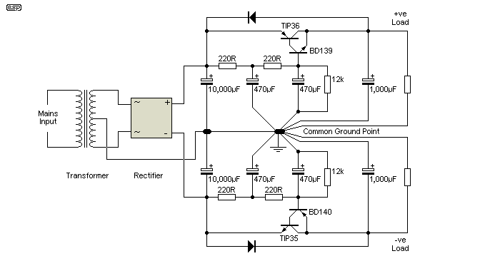
There's one fundamental difference: The ESP capacitance multiplier relies solely on the current gain of the pass transistor. My/PMI's version uses global feedback for increased gain....I'd like to better understand the comparative pluses and minuses of the Mr. Evil and the ESP Capacitance Multiplier Power Supply Filter...
As a result, PMI's will have higher PSRR, and higher input impedance (so smaller capacitors can be used in the RC filter). It's been too long since I did this, so I can't remember how big the difference is. Another difference is that PMI's uses the same topology as an LDO regulator, so the dropout voltage can be lower.
It actually does need adjustment, as noted on that page:The ESP CMP looks so dead-simple with no adjustments or so necessary...
The 12k resistor shown may need to be adjusted to suit your transistors and supply voltage.
Thanks for the quick response! This helps understanding, but I cannot yet judge which one would be the better solution for a 70W power amp module? I just don't know the criteria...
My (existing) Power Amps Modules run the V-Amp Stage with +/-50V supply, the VMOSFET current amplification runs with separate +/-42V.
So...
1. is the higher PSRR of the more complex PMI MP needed/better for the V-Amp stage and why?
2. would the PMI MP also be advantageous for the VMOSFET stage and why?
Thanks for sheding some more light.
Winfried
Either one would work well enough really. Both should reduce ripple by enough that you won't have any audible hum anymore (if you did before). There generally won't be any benefit to using one for an output stage, since those have high PSRR by themselves - just use it for stages with voltage gain.
You can work that out for yourself by measuring how much ripple appears at the output of the amp, and calculating how much would be left if you used a capacitance multiplier, e.g. the ESP version says ~50dB reduction.
The PMI version can be more efficient too, but if you care about that then you would probably be using a class-D amplifier.
I suggest that it would be best to try the simpler ESP version first. That will let you get some experience with how capacitance multipliers work. Then, if you want to learn more, or just want something that's technically better regardless of what the practical benefit is, build the PMI version.

Mr. Evil,
your answer is perfect! I'll do as you suggest and initially build the simpler one(s) for the V-Stage of the Poweramp! Actually, the amp-modules are from an active vintage speaker with inductive motional feedback, which I'm restoring e.g. with a new, stronger power supply and many other things, but that's now really far off-topic 😉 😀
Thank you and best Regards,
Winfried
- Home
- Amplifiers
- Power Supplies
- Simplified MrEvil / PMI Capacitance Multiplier