keantoken said:Ken has a good idea about using matched Fets.
I can't vouch for the THD (though it's below .01%), but this one has virtually infinite input impedance!
EDIT: output impedance is also .05 ohms!
- keantoken
this will work properly only for JFETs with Idss<6mA
Edit: after some analysis it comes to me, that this (the whole scheme) will not work very properly in class AB. Two separate feedback loops will fight against each other resulting in either crossover distortion or hard cross conduction.
Note, that for class AB, the total drop on emitter resistors for high load curent is much higher than for idle conditions.
For AB, you need Schottky diodes, or other nonlinear resistances.
The fixed voltage span between two corrected errors means that
fixed resistor currents will always sum to a constant. AB requires
quiescent current sum less than peak, and thats in direct conflict...
Anyways: So what if diode non-linearity results in "error"? This
does not screw anything up. As long as it is confined narrowly
between the offsets, it can't go anywhere. It just makes the AB
action real smooth, smoothest crossings you have ever seen.
This is a hard crossing?
Attachments
kenpeter said:For AB, you need Schottky diodes, or other nonlinear resistances.
The fixed voltage span between two corrected errors means that
fixed resistor currents will always sum to a constant. AB requires
quiescent current sum less than peak, and thats in direct conflict...
Anyways: So what if diode non-linearity results in "error"? This
does not screw anything up. As long as it is confined narrowly
between the offsets, it can't go anywhere. It just makes the AB
action real smooth, smoothest crossings you have ever seen.
This is a hard crossing?
I wonder if we could use some other device, such as a thermistor, for the "nonlinear" resistances...
I think you should compare your AB Allison side-by side with the usual darlington EF + Vbe multiplier to see how they compare.
- keantoken
In designs with 2 emitter drop span, you can add a front panel
switch to short out the AB Schottky's with .22ohms on demand.
The wire and switch together might even be that many ohms?
Of course, its gonna run a bit hotter in full A.
Not sure which way temperature coefficient of a power Schottky
tries to bend? Need to grab a spec sheet or two and find out.
Just checked, and it goes the wrong way. Hotter raises quiescent.
0.1 ohms pure resistance I left for insurance might be insufficient?
Or just make sure the Schottky's stay cool. Its not like they are
gonna burn more than a half Watt most. And they have big tabs.
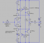
I went off on a tangent, looking into superfast output stage topologies.
I then wanted to know how the Allison might compare bandwidth-wise if I used all 5769/5771 transistors.
The result, is a 1.5Mohm input impedance at 1MHz, 5V pk-pk, and .0027% THD at that same output level!
Into 10Kohms, of course.
Fest your eyes on the beauty. I can now be a zero THD1000 exponent.
I think the usage of bootstrapping here is neat. Obviously, the bootstrap caps are not large because I was only testing it at 100MHz+. 100nF caps can go here if you're working around 1MHz. The bootstrapping is far better an option than a discrete CCS because it has virtually no parasitic capacitance (I consider it necessary).
The 100 ohm resistors help stability a lot. Otherwise, it could oscillate around 500MHz.
- keantoken
Attachments
This design still has nonlinear input impedance, though.
THD at 10MHz into 10k load, 10V pk-pk is .0027% (I misquoted myself earlier).
THD at 10MHz into 10k load, 10V pk-pk with 1k source impedance is .049%
BUT.
THD at 1MHz into 10k load, 10V pk-pk with 1k source impedance, is only .0037%
With 0 ohm source impedance, and the same output levels, this circuit gives .001% THD at 1MHz.
Maximum input impedance is about 2.48 megaohms, which begins to roll off at 200KHz. LF impedance will depend on bootstrap caps but will likely not be able to exceed the 100KHz impedance with modifications, without negatively affecting distortion or bandwidth.
Performance can be improved much by decreasing R8, so that Q7 and Q8 operate farther from 0mA. I consider the current value a safe one.
- keantoken
keantoken said:This design still has nonlinear input impedance, though.
THD at 10MHz into 10k load, 10V pk-pk is .0027% (I misquoted myself earlier).
THD at 10MHz into 10k load, 10V pk-pk with 1k source impedance is .049%
BUT.
THD at 1MHz into 10k load, 10V pk-pk with 1k source impedance, is only .0037%
With 0 ohm source impedance, and the same output levels, this circuit gives .001% THD at 1MHz.
Maximum input impedance is about 2.48 megaohms, which begins to roll off at 200KHz. LF impedance will depend on bootstrap caps but will likely not be able to exceed the 100KHz impedance with modifications, without negatively affecting distortion or bandwidth.
Performance can be improved much by decreasing R8, so that Q7 and Q8 operate farther from 0mA. I consider the current value a safe one.
- keantoken
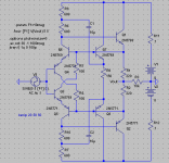
I like your circuit, it's good for a pre amp OP buffer, would be
more difficult to port to power amp. Like a complimentary Rush
cascode - Hugh will like this
")
The bootstrapped CCS-like R's remind me of Greg Balls SKA IP
stage, except I think the separate BJT's (Q7/8) to drive the caps
C1/2 is a better idea. He didn't do this.
How does it perform at 20kHz and say 600ohms.
cheers
Terry
I'm glad you like it.
Rush Cascode, yes, but in complementary configuration. Ultrafast, but odd harmonics are dominant. Even so, THD is vanishingly low depending on your bias point.
With the current component values, THD20 at 30mW into 600 ohms is .00097%. This will get much lower if we move to a CFP or Darlington output stage.
But at audio frequencies, we can afford to use, say, BC547/557C, which gives us 6.9 megaohms of input impedance, and lower distortion. For the output pair we can use 2N5551/5401, and for higher loads the BD139/140.
We can also use discrete CCSs instead of bootstraps since we're not operating at 10MHz anymore.
Another possibility is the usage of THAT packages, which provide good matching, so we can achieve lower offset. But these have rather low gain (just like the 5769/5771).
The Allison will have about the same output impedance as a class A darlington+Vbe multiplier at the same bias.
I have considered using this circuit as an oscilloscope probe, because if the right devices are used you can get input impedances above 20 megaohms.
- keantoken
Here is a file you can play with. Change the file extension to .asc and open it up in LTSpice. I included all the necessary models, since the models I use might not be the default LTSpice models.
According to a AC analysis, input impedance is around 500 megaohms below 10KHz! But if we use anything other than a perfect CCS we soon find this figure is better than can be true.
Output impedance is about 110 ohms.
- keantoken
According to a AC analysis, input impedance is around 500 megaohms below 10KHz! But if we use anything other than a perfect CCS we soon find this figure is better than can be true.
Output impedance is about 110 ohms.
- keantoken
Attachments
Prepare yourself the following spice models:
Small signal BJT 2n4401/2n4403 Qty 20/20
Driver BJT MJE340/MJE350 Qty 5/5
Power BJT 2N3055/MJ2955 Qty 2/2
Power MOSFET IRF540/IRF9540 Qty 4/4
Matched pairs N-JFETs 2N5564 Qty 4 (as 2 pairs)
6DJ8 twin triodes - Amperex... Qty 4 (as 2 twins)
Also:
Potrans Electrical Corporation FS-10024-0M Qty 2 (Rated 24V @ 4.2A each)
Phillips 62,000uF -10%/+75% 25VDCnom/30VDCsurge 85C
w. mounting clamps and covers. Qty 2 (short coke can size)
TO3 Heatsinks w. Sockets Qty 4
6.8uF 100V film caps Qty 4
Fuse kits: Qty2
Any of this crud not useful to you, let me know before it
goes into the mad science bucket. You on your own for
resistors, and wire, and stuff you can find at ratshack...
I probably got appropriate transformers if you prefer
a total linear DIY solution over the switching supplies...
Shottkys & Germanium BJTs, I forget the exact numbers...
Sockets for those 6DJ8's (solder won't stick to tube pins)
Tubes are used/pulls from junked Tektronix oscilloscopes
all tested on B&K mutual conductance and proven good..
kenpeter said:Prepare yourself the following spice models:
Small signal BJT 2n4401/2n4403 Qty 20/20
Driver BJT MJE340/MJE350 Qty 5/5
Power BJT 2N3055/MJ2955 Qty 2/2
Power MOSFET IRF540/IRF9540 Qty 4/4
Matched pairs N-JFETs 2N5564 Qty 4 (as 2 pairs)
6DJ8 twin triodes - Amperex... Qty 4 (as 2 twins)
Also:
Potrans Electrical Corporation FS-10024-0M Qty 2 (Rated 24V @ 4.2A each)
Phillips 62,000uF -10%/+75% 25VDCnom/30VDCsurge 85C
w. mounting clamps and covers. Qty 2 (short coke can size)
TO3 Heatsinks w. Sockets Qty 4
6.8uF 100V film caps Qty 4
Fuse kits: Qty2
Any of this crud not useful to you, let me know before it
goes into the mad science bucket. You on your own for
resistors, and wire, and stuff you can find at ratshack...
I probably got appropriate transformers if you prefer
a total linear DIY solution over the switching supplies...
Shottkys & Germanium BJTs, I forget the exact numbers...
Sockets for those 6DJ8's (solder won't stick to tube pins)
Tubes are used/pulls from junked Tektronix oscilloscopes
all tested on B&K mutual conductance and proven good..
62000uF!? I should protect them from accidental discharge lest I melt my screwdriver.
As far as different trafos, I do prefer linear supplies and all I will probably need is some 79xx ICs, if those 62000uF caps are not enough. I plan on inventing my own linear supply, sooner or later.
The 2Nxx55 transistors are not really what I would use for audio, but I have a nice, HUGE, flyback sitting on my bench from a 1979 TV, just DESERVES adequate accommodation.
But I haven't talked with my friend about this yet. What is our method of transportation?
- keantoken
Transport??? What part of bucket did you not understand?
62,000uF already got safety covers. And mounting hardware.
http://en.wikipedia.org/wiki/2N3055
Suggests these might be the newer expatial type, faster than
the original 2N3055, but with slightly less than full square SOA.
Even so, we are still talking a 115W capable part...
Thats exactly it shown in the picture too... ST Malaysia.
Each got its own individual heatsink, you don't need no
stinkin micas... But you can't let the sinks touch anything
else, especially not the other sink on the other rail...
This will be more a hazard for screwdrivers than the
well covered caps.
Compliment looks exactly the same, except for numbers.
I have a long history with the hurling of sledgehammer heads...
You speak to the re-discoverer the concept of counterweight stall,
and how it relates to the fine tuning of efficiency in such machines.
Not all that different than a mechanized switching power supply
with only one cycle to do the full conversion...
Flashlights I've done, but not yet amplifier parts. Don't temp me...
This is an OnSemi model for the MJ. Can't seem to find an ST...
Not that there'd be much diff... 3055, 4401, and 4403 already
seem to have existing defaults in LTSpice. Gone diggin now to
find .models for those IRFs (So far I have found only subckts)...
.MODEL Qmj2955 pnp
+IS=2.72053e-14 BF=97.7866 NF=0.85 VAF=46.4019
+IKF=2.06624 ISE=1e-16 NE=2.89167 BR=1.32254
+NR=0.834451 VAR=265.121 IKR=2.91618 ISC=1e-16
+NC=2.94268 RB=5.18255 IRB=0.1 RBM=0.1
+RE=0.00048997 RC=0.090446 XTB=1.12701 XTI=1
+EG=1.05 CJE=9.24763e-08 VJE=0.50165 MJE=0.620554
+TF=1e-08 XTF=1.36685 VTF=1.02571 ITF=0.986243
+CJC=5e-10 VJC=0.400266 MJC=0.410181 XCJC=0.803124
+FC=0.671228 CJS=0 VJS=0.75 MJS=0.5
+TR=1e-07 PTF=0 KF=0 AF=1
http://www.diyaudio.com/forums/showthread.php?s=&threadid=16491&highlight=
This thread is interesting. While searching for IRF540 model...
Christer describes how to make subcircuit models to work in
LTSpice...
I've never had any problems doing so before with tube models,
(You can find the 6dj8 triode subcircuit at Duncan Amps). But
the same thing never seems to work for MOSFETs, and only
half the time for IGBTs... I'm still uncertain exactly what I was
doing right when it worked, or wrong when it didn't...
- Home
- Amplifiers
- Solid State
- Simulation Analysis of several unique Allison-based output stages.