")

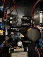
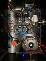
Here's some pictures for motivation of others, again thanks for all the comments and support.
You might question why the 4 JFETs are not populated. I did a dual layout with parallel J113 positions on the top side and parallel 2SK209 on the backside, which is what I populated.
G
You might question why the 4 JFETs are not populated. I did a dual layout with parallel J113 positions on the top side and parallel 2SK209 on the backside, which is what I populated.
G
Attachments
Hi Citation,
Here is the exact schematic, so we can refer to this for better clarity:

R7 & 8 are the large TH resistors you can see in the middle. Each MOSFET needs it's own set of current sharing resistor R9-14 which are surface mount.
Hope that is more clear now. Let me know if you have any other questions.
G
Here is the exact schematic, so we can refer to this for better clarity:
R7 & 8 are the large TH resistors you can see in the middle. Each MOSFET needs it's own set of current sharing resistor R9-14 which are surface mount.
Hope that is more clear now. Let me know if you have any other questions.
G
What Iq are you running? The 0.2R 1W resistors must heat up a bit. They are at 1/2 Iq but but if Iq is 3A, they would be dissipating 0.45W. If the copper that they are soldered to have reasonable area, that would help dissipate the heat though.
It would be interesting to see the FFT plots. I have an interest in noise free amplifiers since I have 103dB speakers. So I like to compare FFTs with amplifier construction techniques, especially wiring and component arrangements. I have my own "must do" items that have worked for me. I do not hear any noise from my speakers. Other builders have done much less than what I usually do and they say that their amps are quiet. But then it depends on the sensitivity of their speakers. Or am I going overboard with the noise abatement measures? I say, better too quiet than not quiet enough. Besides, if you have low sensitivity speakers and your amplifier appears quiet, will it be quiet with high sensitivity speakers? The goal should be to build amps that measure quiet so that they are quiet with high sensitivity speakers.
It would be interesting to see the FFT plots. I have an interest in noise free amplifiers since I have 103dB speakers. So I like to compare FFTs with amplifier construction techniques, especially wiring and component arrangements. I have my own "must do" items that have worked for me. I do not hear any noise from my speakers. Other builders have done much less than what I usually do and they say that their amps are quiet. But then it depends on the sensitivity of their speakers. Or am I going overboard with the noise abatement measures? I say, better too quiet than not quiet enough. Besides, if you have low sensitivity speakers and your amplifier appears quiet, will it be quiet with high sensitivity speakers? The goal should be to build amps that measure quiet so that they are quiet with high sensitivity speakers.
Ben,
Better overkill on the supply and layout even if the amp seems quiet because noise influences the way the amp performs. Case in point are the projects I’ve powered with both traditional powers supples and batteries. The battery power (while having its own noise floor) is just a huge improvement over AC to DC supplies.
Better overkill on the supply and layout even if the amp seems quiet because noise influences the way the amp performs. Case in point are the projects I’ve powered with both traditional powers supples and batteries. The battery power (while having its own noise floor) is just a huge improvement over AC to DC supplies.
Yes, totally agree. Always make it as quiet as possible. Low level details are then more likely to be heard. Lately I have also found that low distortion, but still second harmonic dominant, also helps clarity. Single ended common drain source follower amps over single ended common source amps, with the DIY FE 2022 doing voltage amplification.
Hi Ben,
I think going overboard is part of the DIY fun, gain some knowledge and apply it to everything. Can you hear it or not doesn't really matter, you know it's there even if it can't be heard/measured. Using the SK209 this time is exactly that, I seriously doubt I can hear the difference but I want to try to do it to go a bit overboard, I believe if it was audible Nelson would have released the first design using these parts not the J113. It's just nice to use parts that have the word "audio" on the datasheet... Plus I have a partial reel of them so it was easy for me to go overboard.
G
2.5A, all the measurements and data have been at this for both versions, I haven't tried 3A. So we are talking 1/3W on these resistors, plus as you mentioned I have a lot of copper for them to pour heat into so I don't think it will be a problem.What Iq are you running?
Sure, I'll post them once I measure them, likely this coming weekend.It would be interesting to see the FFT plots.
I think going overboard is part of the DIY fun, gain some knowledge and apply it to everything. Can you hear it or not doesn't really matter, you know it's there even if it can't be heard/measured. Using the SK209 this time is exactly that, I seriously doubt I can hear the difference but I want to try to do it to go a bit overboard, I believe if it was audible Nelson would have released the first design using these parts not the J113. It's just nice to use parts that have the word "audio" on the datasheet... Plus I have a partial reel of them so it was easy for me to go overboard.
G
May I ask how did you get the power supply with battery?Better overkill on the supply and layout even if the amp seems quiet because noise influences the way the amp performs. Case in point are the projects I’ve powered with both traditional powers supples and batteries. The battery power (while having its own noise floor) is just a huge improvement over AC to DC supplies.
Ben & All,
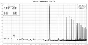
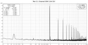
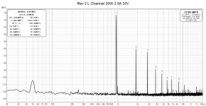
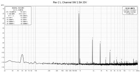
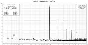
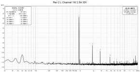
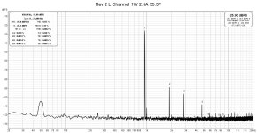
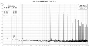
Here are my FFT REW graphs for this new layout.
First some comments:
My testing setup get's setup on the dining table as I don't have space in my office, so I'm not confident of the layout effects and cable routing on repeatablity.
My orginal FFT posting was the Ben's amp only no front end, it also was using aligator clip jumper wires to carry the input. I was in a case but without a top.
This setup was Lenovo laptop running REW -> Topping E30 (output set to 0dB) -> DIY preamp (for level control) -> Amplifier (in a case no jumpers, including front end) -> U-Phoria UM2 ADC -> Lenovo laptop
The Amp was warmed up for 2 hours, but I did run an FFT right after turn on and I didn't see much difference at the lower power level I was using. I used the volume control on the preamp to get as close to RMS voltage target for the desired output as possible but at higher powers it was harder to get excatly there so some variation is likley in the actual output level (no more than 1% RMS voltage)
All measurements were taken at 2.5 amps Iq and 33V (+/- 0.1) SIT Vds.
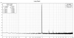
The loopback is included for reference.
Lenovo laptop running REW -> Topping E30 (output set to 0dB) -> U-Phoria UM2 ADC -> Lenovo laptop
Comments always welcome.
G
Here are my FFT REW graphs for this new layout.
First some comments:
My testing setup get's setup on the dining table as I don't have space in my office, so I'm not confident of the layout effects and cable routing on repeatablity.
My orginal FFT posting was the Ben's amp only no front end, it also was using aligator clip jumper wires to carry the input. I was in a case but without a top.
This setup was Lenovo laptop running REW -> Topping E30 (output set to 0dB) -> DIY preamp (for level control) -> Amplifier (in a case no jumpers, including front end) -> U-Phoria UM2 ADC -> Lenovo laptop
The Amp was warmed up for 2 hours, but I did run an FFT right after turn on and I didn't see much difference at the lower power level I was using. I used the volume control on the preamp to get as close to RMS voltage target for the desired output as possible but at higher powers it was harder to get excatly there so some variation is likley in the actual output level (no more than 1% RMS voltage)
All measurements were taken at 2.5 amps Iq and 33V (+/- 0.1) SIT Vds.
The loopback is included for reference.
Lenovo laptop running REW -> Topping E30 (output set to 0dB) -> U-Phoria UM2 ADC -> Lenovo laptop
Comments always welcome.
G
Attachments


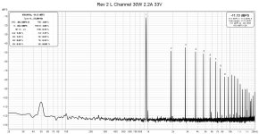
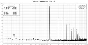
Playing around I also decided to take a look at 2.2A Iq just for fun. With the current BOM I was not able to go lower in Iq as this was the limit of the pot. Although I don't need it, I'll likely keep Iq at 2.5A
40W is not included as I was get big flat tops, showing excessive clipping.
40W is not included as I was get big flat tops, showing excessive clipping.
Attachments


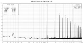
Finally keeping Iq at 2.5A and increasing Vds of the SIT up to 35.3V (+10%)
For my SITs this is relevent as this is the Vds that around were they start out at powering on from cold, before dropping to 33V over a long period.
For my SITs this is relevent as this is the Vds that around were they start out at powering on from cold, before dropping to 33V over a long period.
Attachments

Great DIYing. It's all about trying different things and finding what is best for you.
Your FFT at 1W is similar to mine except yours has higher 3rd harmonic. I use a separate oscillator and it has much lower distortion than the REW derived signal. One major difference though is my setup was cleaner at high output. By cleaner I mean the level of distortion dropped more as the order of the harmonic increased. I am not sure whether that is due to the lower distortion oscillator or due to something else. But the differences are not that great. I am sure the amp sounds great.
Is your power supply -60V and is that also powering the FE?
My THF-51S Mu Follower Follower FFTs
This set of FFTs was done with the DIY FE 2022. Maximum output was 35W, limited by the gain of the FE and the maximum output voltage of the oscillator. There is a bit of power supply noise showing but they are not audible with my 103dB speakers. They are there possibly because of my oscillator being AC powered, arrangement of components and AC cables during the test, and also due to the amplifier power supply. This amplifier started out years ago as a version of Nelson's BAF2015 Single Ended common source mu follower. The power supply filter board was point to point wired on perf board. I knew much less then than I do now on how to build a quiet amplifier so it started out noisy. That forced me to learn how to build a quiet amplifier. I learned about loop areas, modified the power supply filter board so that I could no longer hear any noise. It may still be improved upon. I should replace the filter board with the power supply pcb that I had designed when I converted the amp to common drain.
Last edited:
As for FFT and noise, I usually look at the 1W FFT and see what the noise level is relative to the 1W primary frequency. For instance my right channel 1W FFT showed 60 and 180 Hz at about -108dB, and the 1kHz at -17.4dB, for a difference of about 91dB. The left channel was even better with the noise at about -119dB and the primary 1kHz at -17.5dB, for a difference of about 101dB. All of this noise is inaudible with my ear up against my 103dB speakers.
Hi Ben,Is your power supply -60V and is that also powering the FE?
Generally yes to both, although when I measured it before it was closer to -61V but that was before I tuned in the Iq (I think Iq was around 2.4A when I measured it), so it may be slightly lower now. I made a CRCLC filter for the PS, maybe for better filtering but also to drop the voltage a bit as I'm using Schottky diodes for rectification and they will drop a little less voltage (and less heat!)
As mentioned I had to use a pre-amp with voltage gain to drive this to clipping, which is not how I use it when listening to music.
My currently listening setup a quad AD1862 (two per channel) DAC -> Abraxalito's Dark LED IV -> B1 Buffer with volume control -> MuFo amp w/ FE2022.
Yes it sounds really great. Super fast and dynamic. As mentioned, I don't hear any noise from the speakers. I believe this design is quite immune to noise, as my previous messy layout was also audibly quiet at reasonably high efficiency speakers.
The FFT above you can see distortion in the loopback, this loop back didn't have the preamp in the chain. I assume the preamp at higher output is amplifying the DAC distortion, plus I'm sure adding some of it's own. The ADC I'm using is not nearly as good as yours as the noise floor is much higher as well.
I'm using only 43K ohms in the gain stage of the FE, which is less than half the original design, as I am not running standard output voltages from the DAC. It's about double the standard.
G
It seems that my experience with noise is a bit different from yours. But then it depends on the sensitivity of the speakers. My speakers have a sensitivity of 103dB and if noise is present, I hear it. Because of that, I have refined my construction technique over time so that I do not hear any noise when my system is powered up with no music playing.
- Home
- Amplifiers
- Pass Labs
- Single Ended Tokin SIT THF-51S Common Drain Mu Follower Amplifier, 45W?