Rudolf, I simulated the circuit on page 1, and the DAC input is approx at the same voltage as the diodes on the common base transistor.
You said that the 2 red leds should be replaced by a 1n4148 diode when using a TDA1541
This will put the input at 0.7V, but this dac (I think) should be used with its output on virtual ground. Are you sure for the 1n4148 diode?
You said that the 2 red leds should be replaced by a 1n4148 diode when using a TDA1541
This will put the input at 0.7V, but this dac (I think) should be used with its output on virtual ground. Are you sure for the 1n4148 diode?
Yesterday I adjusted the SE output stage according to Rudolf´s post (#68). Current through R22 is now approx. 1,1mA, with RSO1A at 180R Uout is at about 7,5V. I couldn´t fine tune this value because I had no suitable potentiometer at home.
Hum is slightly less now, but still there. Powered by a 12V battery the hum is gone, and as good as I can tell by listening to one channel only, sound is really sweet compared to the opamp I/V stage (AD712, muting transistors removed, no output caps).
Output is definitely lower than with the opamp, could I increase it by increasing Riv by a factor of Iout1543/ Iout1545, this is 2,3/1 and gives Riv at 2,3*1,5=3k45? What value should be Civ then?
What can I do to get rid of the hum without using battery power?
Michael
mihu said:Yesterday I adjusted the SE output stage according to Rudolf´s post (#68). Current through R22 is now approx. 1,1mA, with RSO1A at 180R Uout is at about 7,5V. I couldn´t fine tune this value because I had no suitable potentiometer at home.
Hum is slightly less now, but still there. Powered by a 12V battery the hum is gone, and as good as I can tell by listening to one channel only, sound is really sweet compared to the opamp I/V stage (AD712, muting transistors removed, no output caps).
Output is definitely lower than with the opamp, could I increase it by increasing Riv by a factor of Iout1543/ Iout1545, this is 2,3/1 and gives Riv at 2,3*1,5=3k45? What value should be Civ then?
What can I do to get rid of the hum without using battery power?
Michael
As I posted earlier, the Philips CD713/723 players are using 3k3 and 220pF for I/V conversion. Your Marantz CD38 circuits are almost identical.
But, you do need a higher supply then, which probably is not available.
I've got no 100Hz problems, don't understand why you're having problems. If you start using a regulated supply, it needs to be higher again to compensate for the drop over the series regulator.
You do have capacitance after the rectfiers for your raw supply I hope ? You can increase it to lower ripple.
Since current draw is constant, you could also use a capacitance multiplier for minimal drop.
I do suggest another fet with lower IDDS (and low GOS) to replace your BF245B.
My suggestions are: J202, BF245A, J113, 2n5484
What are the current VGS and VDS when it's set for 1.1mA ?
The 180 ohms for RSO1A seems a bit high...
Hi Mihu & Rudolf
If Mihu is getting 2V on led and rudolf 1.5V would this explain the difference in the RS01A ?
Although this hum thing should not be there ultimately you may well find that you prefer the sound of batteries in which case the hum problem is not a problem
mike
If Mihu is getting 2V on led and rudolf 1.5V would this explain the difference in the RS01A ?
Although this hum thing should not be there ultimately you may well find that you prefer the sound of batteries in which case the hum problem is not a problem
mike
rbroer said:
As I posted earlier, the Philips CD713/723 players are using 3k3 and 220pF for I/V conversion. Your Marantz CD38 circuits are almost identical.
But, you do need a higher supply then, which probably is not available.
I've got no 100Hz problems, don't understand why you're having problems. If you start using a regulated supply, it needs to be higher again to compensate for the drop over the series regulator.
You do have capacitance after the rectfiers for your raw supply I hope ? You can increase it to lower ripple.
Since current draw is constant, you could also use a capacitance multiplier for minimal drop.
I do suggest another fet with lower IDDS (and low GOS) to replace your BF245B.
My suggestions are: J202, BF245A, J113, 2n5484
What are the current VGS and VDS when it's set for 1.1mA ?
The 180 ohms for RSO1A seems a bit high...
Rudolf, can you answear my question?
rbroer said:
As I posted earlier, the Philips CD713/723 players are using 3k3 and 220pF for I/V conversion. Your Marantz CD38 circuits are almost identical.
OK, I didn´t get this the first time, sorry.
If I understand correctly, my hum problem is a result of using lower supply voltage and a less suited fet than you suggested which is a really bad combination.
I´ll try to replace the fet first, if it doesn´t solve the problem I´ll use a dedicated power supply at a higher voltage. If the hum is still there after that, I´ll use a regulated PS.
You do have capacitance after the rectfiers for your raw supply I hope ?
Yes, it´s the V+ supply of the (removed) I/V opamp. I also tried 470µF direct on the veroboard, didn´t make a difference.
What are the current VGS and VDS when it's set for 1.1mA ?
I´ll check that, probably can´t do it before monday :-((
I measured the 1.1ma through R22 with RSO1A still at 83R, before adjusting Uout.
I've got no 100Hz problems, don't understand why you're having problems
Maybe that´s because you know what you are doing and I´m only copying without really understanding what I´m copying. But I´m learning and enjoying ;-))
Michael
OK, couldn´t wait, squeezed out a few minutes and measured all the voltages. Supply is 12,76V, RSO1A is 148R, BF245"B" instead of "A", R22=2k64//5k52=1k79, green LEDs.
Voltages at nodes right part of schematic: 0V D5 1,89V D4 3,80V D3 4,47 R22 6,66 BF245B 10,16V D2 10,82V D1 12,76
Voltages in left part at C and E of transistors: 0V RSI1 1,165V Q5 3,07V Q4 3,75V Q3 7,93V Q2 10,84 Q1 11,52 RSO1A 12,76V.
I hope this doesn´t create too much confusion, I´ll make a drawing ASAP.
Michael
Michael,
my working values are very similar to yours.
Rudolf,
I miss the point of using a lower IDSS fet: since the base voltages of Q2 and Q3 are fixed the current source will work well if you leave it some volts for VDS... are there other reasons I'm not considering?
Cheers
Andrea
my working values are very similar to yours.
Rudolf,
I miss the point of using a lower IDSS fet: since the base voltages of Q2 and Q3 are fixed the current source will work well if you leave it some volts for VDS... are there other reasons I'm not considering?
Cheers
Andrea
Voltages seem ok Mihu.
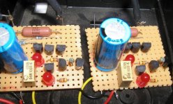
I just opened the player, I noticed I used red LED's in stead of greens.
In fact the color isn't that important...
Hooked it up, cranked the amp fully open, no hum problems here.
You either have an enormous ripple on your supply, have a very high gain on your amp, picking up hum through your wiring or are doing something wrong.
Simulation also verifies correct operation without hum problems' ripple surpression is about 150 times.
Best jfets for CCS are ones that have low gos and low Vgs(off) Andrea.
Attachments
rbroer said:Voltages seem ok Mihu.
I just opened the player, I noticed I used red LED's in stead of greens.
In fact the color isn't that important...
Best jfets for CCS are ones that have low gos and low Vgs(off) Andrea.
I also noticed that the color doesn't match that much with the voltage drop of the diodes... I have some green leds with 1.85V and red ones with direct voltage varying from 1.65 to 1.9V depending on the type... at the end I used 3 mm red ones with the lowest voltage drop.
About the JFets I agree that a lower Idss fet is better (in case the current needed is low enough
") ) than a higher Idss type because the current source can work well at lower voltages, however in this case we have enough Vds to make a CCS with a "C" type .
) than a higher Idss type because the current source can work well at lower voltages, however in this case we have enough Vds to make a CCS with a "C" type .Is the "gos" the key factor?
Another question: since I wil be using battery power the optimal setting for the idle voltage on Riv, in my case, has to take in account the worst case (i.e. battery almost completely discharged, say 11V).
As a general rule (correct me if I'm wrong) we should trim the upper CCS to have a "idle" voltage on Riv (with the DAC attached!) at halfway between the emitter voltages of Q2 and Q3 to obtain the maximum output voltage swing available.
Given a full scale current of 2,65 mA the voltage swing on the Riv is 2,65*1,5k = 3,975V Pk-Pk.
Leaving 1V to both Q2 and Q3 to avoid saturation we need at least 6V between their emitters to have a "linear" behaviour of the I/V stage, and using Led current sources this gives a minimum Vsupply of about 11.3V.
Slightly relaxing these worst-case conditions (or using 2 1n4148 diodes in series instead of the leds and changing accordingly the resistors of the current sources/sinks) I'd conclude that a battery supply is suitable for this circuit.. do you agree?
Cheers
Andrea / that sometimes uses the forum to force himself to think
Rudolf and All,
my output stage is finally working! I changed my BF245"B" for the suggested "A" type and use red LEDs now, and the hum is gone!
I adjusted voltage OUT1 to 7V, as Rudolf recommended right in the middle between VB(Q2) at 10,5V and VB(Q3) at 3,6V. Then I played music and turned the Pot in both directions until I got distortion, then adjusted between these extremes and ended up at 7,5V Vout1.
I could only listen to it for some minutes today morning so I can´t really tell yet, but there is more detail and soundstage got more depth. Maybe there is a little more background noise than with the AD712 opamp output, but all in all definitely better.
Thank you for sharing this circuit and for your patience and help!
Michael
mihu said:my output stage is finally working...
and the hum is gone!
Now that wasn't too difficult, was it
Considering the ripple on the supply;
I noticed I used 1000u per channel, so that is 2000u total
Mihu, after getting used to the sound you can tweak some further by increasing the current sink, by lowering that 270 ohms RSI1 resistor.
If I remember correctly I used 100 ohms for RSI1, that's about 10mA. The upper current source shall need to be increased of course by lowering (potentiometer) RSO1.
IMHO, it's a minor improvement.
You might even try replacing Q3 and Q4 with bjt's some inmates consider better like 2SC2240BL or 2SC2547E.
I'm out for about a week, so won't be able to answer any questions.
In the mean time, happy DIY,
Heiko said:Hi!
The TDA1545 has about 3.2 V on its current outputs. How important is it to keep the input of the output stage at this voltage? What tolerances are possible?
Heiko
The current outputs don't have a fixed voltage output, the voltage is set once you set the load, a resistor in case of passive I/V.
The TDA1545 and 1543 work well if the current output node works at a voltage between 1.8V and Vcc - 1.2, as both Rudolf and Michael pointed out.
This means that you can happily use this I/V converter with your TDA1545 with no modifications (just set the currents and the Riv accordingly).
Cheers
Andrea
Listening impressions
Yesterday I had the chance to listen to this I/V stage in my TDA1543 DAC (with ASR), and even if I couldn't compare it directly to my other implementation (4 paralleled TDA1543 running at 8.5V with passive I/V) I must say that it performs very well.
I had the impression that with this I/V the 1543 is a bit more mellow, more soft than the paralleled DAC solution, while maintaining most of its characteristics (after all the same chip is used in both..);
The bass is less tight (maybe too much ), but depending on the setup (amp, speakers) this might become an advantage.
In my friend's setup I like the Dac tower most, but when my speakers will be ready I might change my mind so for now I left both stages (fed by the same signal) inside my Dac's cabinet.
Did anyone else build this stage? Impressions?
Cheers
Andrea
Yesterday I had the chance to listen to this I/V stage in my TDA1543 DAC (with ASR), and even if I couldn't compare it directly to my other implementation (4 paralleled TDA1543 running at 8.5V with passive I/V) I must say that it performs very well.
I had the impression that with this I/V the 1543 is a bit more mellow, more soft than the paralleled DAC solution, while maintaining most of its characteristics (after all the same chip is used in both..);
The bass is less tight (maybe too much
), but depending on the setup (amp, speakers) this might become an advantage.In my friend's setup I like the Dac tower most, but when my speakers will be ready I might change my mind
so for now I left both stages (fed by the same signal) inside my Dac's cabinet.Did anyone else build this stage? Impressions?
Cheers
Andrea
Andy, I built the SE I/V stage and tested it in my Marantz CD38. I guess I´m still doing something wrong, but in my implementation it is noisier than the original opamp output stage. The best I can describe this noise is something like tape hiss.
I use a dedicated unregulated analog PS, GND connected to player GND at the DAC chip. From there seperate GND wires go to 5V regulator for DAC, I/V left channel, I/V right channel and cinch socket (socket not connected to player chassis).
Now I´m looking forward to Rudolfs PCBs for the SuperPair I/V which should arrive soon and give me less options to do something wrong ;-))
Michael
- Status
- This old topic is closed. If you want to reopen this topic, contact a moderator using the "Report Post" button.
- Home
- Source & Line
- Digital Line Level
- Single rail, active I/V for TDA1543, TDA1545A