I personally trust this seller. To give you an example, he also sells stuff not on fleaBay and if the transistors he can't get NOS and he think they will be fake he just don't sell them and he will try to get used pulls. This is a personal thing I know but he never ever sold me a part that was not genuine. He's actually the only seller I will trust for this.
But I'm talking for myself and will not take any responsibilities for anything.
Ciao!
Do
But I'm talking for myself and will not take any responsibilities for anything.
Ciao!
Do
Wow, how many BJT and MOSFET have you bought from Jim's Audio? I know he has been accused of pirating the DX Blame MXIII boards. I hope you are right about his devices being genuine.
Don't worry about it mate, I totally dig where you're coming from with fleaBay. I guess to each his own experience and I wouldn't want anyone to point fingers at me afterwards.
")
Ciao!
Do
Member
Joined 2009
Paid Member
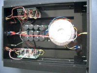
For those in the area for a DIY meet in the Vancouver area.I will have my Greg Ball amp with my Bent Audio Pre at this event for people to listen to.
http://www.diyaudio.com/forums/clubs-events/236814-fraser-valley-vintage-audio-fair-2.html
SKA sponsored Audio Forum - Products
BentAudio.com :: TAP
http://www.diyaudio.com/forums/clubs-events/236814-fraser-valley-vintage-audio-fair-2.html
SKA sponsored Audio Forum - Products
BentAudio.com :: TAP
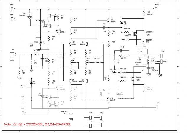
For those who bought the boards I had talked about, I just received an urgent update and you should have too but there is a critical change to be done, Q1 to Q4 uses 2SC2240BL/2SA970BL or compatible (pinout).
According to the author, here's what happened
"I did three versions of layout, one using BC, and the other two using Japan transistor, and I fab the Japan ones instead." ... "but misplaced the BC BOM into the documentation."
Ciao!
Do
According to the author, here's what happened
"I did three versions of layout, one using BC, and the other two using Japan transistor, and I fab the Japan ones instead." ... "but misplaced the BC BOM into the documentation."
Ciao!
Do
Last edited:
You would have to sort through forum posts on the SKA forum to find Greg Ball's specifications and test results for the original GB150 and developments to get that information. SKA sponsored Audio Forum - IndexCan wee see the bode plot for OLG and CLG of this amplifier ?
Greg was a member of DIYAudio forum several years ago. You may find some preliminary discussion and results then, under his user name: Amplifierguru.
Last edited:
Member
Joined 2009
Paid Member
When it comes to bode plots I tried running some simulations. This amp is unlike other amps I've simulated. The frequency response is quite extended and the OLG is high for sure. In the end I decided that my Spice skills weren't up to the task - there are sophisticated approaches to looking at stability in spice that I don't fully understand. So I haven't kept much of that information and hence don't have pictures to post. What I was able to see from the phase of the output, is that the simulation confirms the value of the feedback capacitor (published as 6pF) must be in the range that Greg specifies - too low is bad, and higher values slowly erode stability margins. I was looking into a resistive load mind you, I haven't tried simulating with a more realistic load.
For those who bought the boards I had talked about, I just received an urgent update and you should have too but there is a critical change to be done, Q1 to Q4 uses 2SC2240BL/2SA970BL or compatible (pinout).
According to the author, here's what happened
"I did three versions of layout, one using BC, and the other two using Japan transistor, and I fab the Japan ones instead." ... "but misplaced the BC BOM into the documentation."
Ciao!
Do
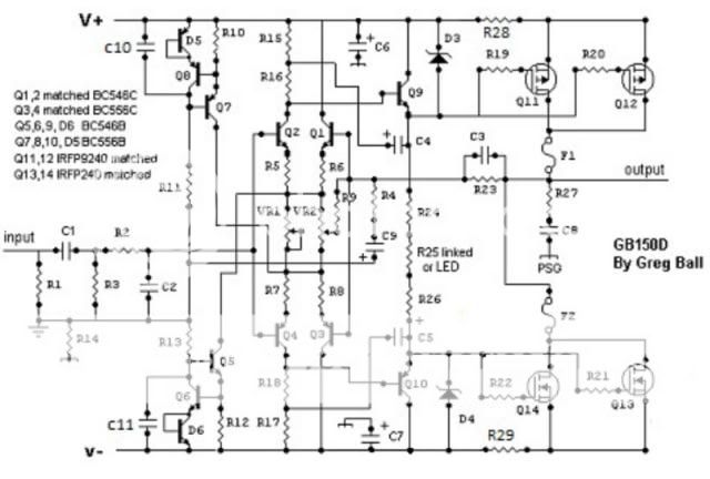
Obviously not the sharpest pencil in the box. Rather than design for the very obtainable BC546/556, as Greg did, he designs for an obsolete part. I guess it would seriously affect his sales if he made that known to prospective buyers.
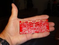
These boards are tiny. Where the originals this small? I have found the 2SC2240BL/2SA970BL units on ebay so I guess I'll go that route. I didn't notivce that Greg called out 546c/556c for Q1&2 and 546b/556b for the others. I suppose the 2SN's will be just as easy to source.
Thanks, Terry
Thanks, Terry
Attachments
BC556C
Electronic Component Distributors - Resistor & Capacitor Distributors - Obsolete Electronic Components - Discrete Semiconductor Distributors - Integrated Circuit Distributors - Quest Components still has Fairchild BC556C, they quoted me $ 0.0800 for 1000 pieces but shipping to me in Singapore was $50!
Electronic Component Distributors - Resistor & Capacitor Distributors - Obsolete Electronic Components - Discrete Semiconductor Distributors - Integrated Circuit Distributors - Quest Components still has Fairchild BC556C, they quoted me $ 0.0800 for 1000 pieces but shipping to me in Singapore was $50!
These boards are tiny. Where the originals this small? I have found the 2SC2240BL/2SA970BL units on ebay so I guess I'll go that route. I didn't notivce that Greg called out 546c/556c for Q1&2 and 546b/556b for the others. I suppose the 2SN's will be just as easy to source.
Thanks, Terry
From memory they were pretty close to that size.
that's $130 to your door for 1000 off BC556c.
You could sell these on in swap meet in batches of 10 @ $1.30 + post and packing and recoup your costs without any loss.
Thanks AndrewT, very thoughtful suggestion.
According to the quotation questcomp sent, there is an availability of 27000+ Fairchild BC556CTA (datecode 2010+). I'm sure that's plenty enough for everyone looking to build the GB150Ds.
While looking over the schematic and BOM for the Jim' Audio boards and comparing them to Greg's schematic, I see that he added a couple of resistors, R30 and R31 and reduced the values of R11 and R13 Anyone know if this was an upgrade done by someone at the SKA forum or just something Jim's Audio came up with? I could easily just jump R30and R31 and go with the other values.


- Home
- Amplifiers
- Solid State
- SKA GB150D now public domain...