")
Nattaw wrote: When the rail voltage goes way down while reservoir caps drain the storage, there could be a moment the front end stages drop out of their designed working conditions far enough, and from that moment on the feed back loop no longer have sufficient phase margin to stay stable. An oscillation would start. That is probably what you heard. This behavior is part of the reasons many speaker protection designs would cut out speakers early at power off, and delay speaker connection at power on.....So that you would not hear it.
Do you think that a loadspeaker protection/delay will solve this problems.
On my two power uits a 530 Kohm resistor is connected to a 1.5 uF/100 bipolar condenser to zero(0V). Is this a kind of bleeder. Usually I use a 2.2 Kohm resitistor from +/- to Zero(0V).
This question go to jwilhelm:
I tested the second channel with Spooky today. After the buble test (ok) I connected to my vari trafo. Reaching +/- 45 V DC, the bias was 10 mV over one emitter resistor. Bias pot was in the 500 ohm position. Increasing the voltage the bias went to high.
I remember that I had the same problem with my first Slewmaster . I then increased the resistor that is connected to the bias pot and solved the problem that way. But I can not remember what resistor I increased. Was it R107 (470 ohm)? Or is it better to increase bias pot to 1 Kohm?
As you can read from my earlier post the "second" Spooky IPS measured as it should. So that is not the reason for the high bias.
Eivind S
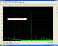
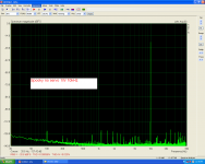
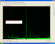
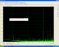
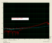
As my spooky has been modified for non servo function the first test was as it.
Power supply=+/-50v
75000uf/rail
offset=15mV
Idle current=0.015v/0.33R=45mA/piese or 90mA/Pair
Power supply=+/-50v
75000uf/rail
offset=15mV
Idle current=0.015v/0.33R=45mA/piese or 90mA/Pair
Attachments
Guy's, plse help.
Is the Slewmaster still an EF3 when using vertical mosfets on the OP stage without the predrivers that is dropped when using mosfets ?
EF3 means three stages of current gain through emitter followers. The only actual emitter follower in your output would be the drivers so it's really an EF1.
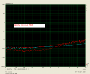
As my spooky has been modified for non servo function the first test was as it.
Power supply=+/-50v
75000uf/rail
offset=15mV
Idle current=0.015v/0.33R=45mA/piese or 90mA/Pair
Looks pretty good without the servo! Is this with the feedback ground connected to the lifted input ground?
Is your software set up properly? In the first graph, shouldn't the 1k spike peak at 0db (I'm still trying to figure out how to use the software)?
Do you think that a loadspeaker protection/delay will solve this problems.
Eivind S
It depends. If hearing the oscillation is the problem, a loudspeaker protection/delay will solve it. If the oscillation itself is the percepted problem, a loudspeaker protection/delay does little if not nothing to help.
Extra circuitry is sometimes employed to avoid the oscillation, such as quickly cutting off the tail current supply to the input transistor pair at power off. But I guess in most cases the oscillation on residue supply is benign, and disconnecting the loudspeaker is all it takes to not get bothered.
Thanks Jeff. This is an interesting post that I found. It seems the ef3 needs 4.5mA bias from the Ip stage. Os states that an ef2 needs 8mA. Does that mean an ef1 needs even a higher current ?
Quote:
Originally Posted by still4given
Please excuse the ignorance. Does raising and lowering the the bias on the OPS affect the current output of the IPS?
Nope , the extremely high Z of the EF3 has little effect on Ivas.
Ivas should only be altered by the adjustments or slightly by temperature.
An EF2 , like the badger, will be far worse .... why we run the badger at
8ma+ .... ( also , for OPS "droop").
Vrystaat, you were speaking of using MOSFETs which don't require the same drive as do BJTs.
It was determined that simply driving the MOSFET gates through one emitter follower (the predrivers) was all that was really needed. It had been tested with both the predrivers and the drivers feeding the gates (EF2) but the gain in performance was so minute that it was felt that going with the EF2 as a buffer was unnecessary.
Also, using vertical MOSFETs is not something ostripper really ever intended. That was something vzaichenko and myself were thinking and tinkering with mutually. We also found suitable modifications for the bias generator incorporating an LED when using MOSFETS.
Thanks Jeff. This is an interesting post that I found. It seems the ef3 needs 4.5mA bias from the Ip stage. Os states that an ef2 needs 8mA. Does that mean an ef1 needs even a higher current ?
Quote:
Originally Posted by still4given
Please excuse the ignorance. Does raising and lowering the the bias on the OPS affect the current output of the IPS?
Nope , the extremely high Z of the EF3 has little effect on Ivas.
Ivas should only be altered by the adjustments or slightly by temperature.
An EF2 , like the badger, will be far worse .... why we run the badger at
8ma+ .... ( also , for OPS "droop").
The base of a BJT transistor requires current flow to emitter to cause current flow from collector to emitter. The gain of the transistor tells you the ratio of current amplification. For example if the transistor has a gain (hFE) of 100, 10mA current flow through the base should cause 1A to flow collector to emitter.
With mosfets the only current that flows through the gate is what is required to charge or discharge the capacitance of the gate. They don't pass current to their source as a BJT transistor does. They are voltage controlled, not current controlled. They don't require nearly as much current to operate so they don't add a heavy load to the VAS section of the amplifier. They do require a very fast driver stage to keep them under control though, otherwise they will suffer shoot through and self destruct.
Guy's, plse help.
Is the Slewmaster still an EF3 when using vertical mosfets on the OP stage without the predrivers that is dropped when using mosfets ?
EF3 means three stages of current gain through emitter followers. The only actual emitter follower in your output would be the drivers so it's really an EF1.
you are getting confused.Thanks Jeff. This is an interesting post that I found. It seems the ef3 needs 4.5mA bias from the Ip stage. Os states that an ef2 needs 8mA. Does that mean an ef1 needs even a higher current ?
Quote:..........
Please excuse the ignorance. Does raising and lowering the the bias on the OPS affect the current output of the IPS?
Nope , the extremely high Z of the EF3 has little effect on Ivas.
Ivas should only be altered by the adjustments or slightly by temperature.
An EF2 , like the badger, will be far worse .... why we run the badger at
8ma+ .... ( also , for OPS "droop").
EF = Emitter Follower. That applies to a BJT.
For a mosFET the equivalent is a Source Follower (SF).
If you combine a single EF with a single SF you end up with two stages of current multiplication.
Similarly you can combine any three from EF and SF and you get three stages of current multiplication.
The combining of multiple stages increase the phase shift through the whole stage and this increases the complexity of the compensation required to maintain the same stability margins.
EF1 is easiest.
EF2 has more phase shift.
EF3 has the highest phase shift.
EF4 is extremely rare.
Swapping in a faster mosFET may make compensation easier because the faster device reduces the phase shift. But equally the faster device allows extended bandwidth and that can be more difficult.
This BJT explanation is misleading.The base of a BJT transistor requires current flow to emitter to cause current flow from collector to emitter. The gain of the transistor tells you the ratio of current amplification. For example if the transistor has a gain (hFE) of 100, 10mA current flow through the base should cause 1A to flow collector to emitter.
With mosfets the only current that flows through the gate is what is required to charge or discharge the capacitance of the gate. They don't pass current to their source as a BJT transistor does. They are voltage controlled, not current controlled. They don't require nearly as much current to operate so they don't add a heavy load to the VAS section of the amplifier. They do require a very fast driver stage to keep them under control though, otherwise they will suffer shoot through and self destruct.
BJT are voltage to current devices.
Apply a voltage across the BE junction the the device passes current from C to E. As a consequence of that CE current there is a parasitic current that has to flow into or out of the base.
That parasitic current is missing in a mosFET. But the mosFET gate still passes some current. It is not zero. This capacitance charging/discharging current is almost identical between BJT and FET devices.
Jwilhelm wrote: When you adjust the pot does bias raise smoothly or does it suddenly shoot up?
Yes, when I keep the power voltage steady on +/-45 V DC I can raise the bias smoothly. But as soon as I raise the voltage a couple of volt with the variotrafo, the bias over one emitter raise to 60mV. I stopped there. Did not take the chanse to raise the power higher up.
Eivind S
Yes, when I keep the power voltage steady on +/-45 V DC I can raise the bias smoothly. But as soon as I raise the voltage a couple of volt with the variotrafo, the bias over one emitter raise to 60mV. I stopped there. Did not take the chanse to raise the power higher up.
Eivind S
Last edited:
Jwilhelm wrote: When you adjust the pot does bias raise smoothly or does it suddenly shoot up?
Yes, when I keep the power voltage steady on +/-45 V DC I can raise the bias smoothly. But as soon as I raise the voltage a couple of volt with the variotrafo, the bias over one emitter raise to 60mV. I stopped there. Did not take the chanse to raise the power higher up.
Eivind S
It's odd that you are seeing such high bias current. I misread the schematics in all of the Slewmasters I built and ran fine with 200R pots installed. You may have already mentioned this but I'm viewing this from a phone. What version of output board are you using and what did you choose for outputs, drivers and bias transistors?
Unfortunately the Spooky boards don't give an easy place to measure in circuit VAS current. What is your current flow through R25 and R29? It appears they should be passing VAS current + 3mA by the voltage readings on the schematic. I'm wondering if this is increasing unproportionally when voltage increases.
Last edited:
- Home
- Amplifiers
- Solid State
- SlewMaster Builds