Have a look at these mods to the current CFA-XH boards. Some value changes aren't shown but the cuts and jumpers are.
Let me know if you see something I missed.
I'm not advocating that we follow this direction but since I have extra boards I want to try it. DIYA baby!
That looks like it ...

You are right on top of things , terry !!
This is a safe mod , I ran the hell out of the sim. It works and
definitely performs quite a bit better. (nothing is lost).
don't forget the 10k's from Q1/2 collectors to the hawksford CM's !
OS
Last edited:
Sorry OS that I didn't respond back,
I really don't want to be too complicated on the layout so I just going to ask you simple questions, man I know you are rolling with new IPS wow! I don't want to bother you too much
ok I'm making a pretty look of Wolverine V1.2 "for myself of course lol" I know there is version 1.3 and I can do that later, but example to be simple if I put it it together all parts all good to go then I can just use the "OPT1" ("I think is a jumper that goes there I'm not sure to be honest") then DSC=MMSD4148 is use and OPT2 is not in use ? I like more the DSC option to use
I really want it to make sure what I'm thinking is correct
sorry for any grammar errors
Juan
No opt 1 - I think 5th element had no issue with it (Q3 cascode reference).
And just the diode.. (select a nA to pA reverse leakage one) with no opt
2 will be fine.
You will then have 5th elements .0005% thd. (he tested)
OS
No opt 1 - I think 5th element had no issue with it (Q3 cascode reference).
And just the diode.. (select a nA to pA reverse leakage one) with no opt
2 will be fine.
You will then have 5th elements .0005% thd. (he tested)
OS
Thanks to clear that out, good to go then yes !
"contra"! = damn ! .0005% THD that is habichuelas = " beans" good with me
I see Terry having fun that is good
Juan
Member
Joined 2009
Paid Member
Cool, I'll built it today. If I have all the parts it will be playing tonight.
Thanks, Terry
Welcome to the group Terry, is this your first time ?
Hi, my name is Terry. I build an amplifier every day. I can't help it. I just can't stop. I need your help.
Thank you for sharing Terry. We all understand. We are here to help. The first step is admitting that you have a problem.
Where's my soldering iron ?

I would if there was one around that threw out stuff like that.
A while back I had some old computers and TV sets that I needed to get rid of and so I took them to a recycler at a mini-storage place. He had me unload them into a storage contaner. Man, that thing was full of old stereo equipment. All I could see was possible transformers and heatsinks. One way deal there though. Unloading only.
A while back I had some old computers and TV sets that I needed to get rid of and so I took them to a recycler at a mini-storage place. He had me unload them into a storage contaner. Man, that thing was full of old stereo equipment. All I could see was possible transformers and heatsinks.
One way deal there though. Unloading only.Phillips 5 channel surround receiver = 400VA 35-0-35V toroid.
Good for my slews until I buy at least a 50-0-50 from antek.
And , the Z-5500 sub had the 300va 30-0-30V toroid. I
might have to use one of my Badger PCB's (no multiplier/cascode V drop).
All free. I did scrap (for $$ -100lbs) many EI trafos of 30-40V range .
Many Sanken output trannies , too... all good , all free.
OS
Good for my slews until I buy at least a 50-0-50 from antek.
And , the Z-5500 sub had the 300va 30-0-30V toroid. I
might have to use one of my Badger PCB's (no multiplier/cascode V drop).
All free. I did scrap (for $$ -100lbs) many EI trafos of 30-40V range
. Many Sanken output trannies , too... all good , all free.
OS
My amplifiers have ground loop breaker circuits and the computer is galvanically isolated from the signal source. This, in general, keeps ground loops to a minimum, where if the galvanic isolation wasn't present the measurements would be screwed up (I know this because the isolator was put there specifically to break this loop).
Can you give a schematic?
I can't solve this problem .
Also i tried power the pc via UPS not connected to main outlet, but with the same results.
The isolator in question is a digital one. I modified the sound card to output the digital audio I2S lines via LVDS. This then travels down a pair of network cables (surround sound) to an outboard box. This box contains the digital isolator and breaks completely breaks the ground connection with the PC.
Apart from that though every device within my hifi/measurement setup uses (where applicable) these circuits from Rod Elliotts website. Figure 4.
Earthing (Grounding) Your Hi-Fi - Tricks and Techniques
Even without the digital ground loop breaker it is possible to get good results from the PC if everything else within the system has loop breakers.
OS,
Thanks for the comments. I think as nice as it is to keep lowering the thd of this CFA-XH that there must come a point where none of us are going to hear much of any difference. At the same time a significant lowering of the noise floor due to the psrr getting so much better we would probably notice that, correct me if I am wrong.
Jason,
No problem on your boards as you have made them. Since it seems to be a simple mod to your current boards for prototyping they will still be more than great. Next round it would just be nice to have that change added to the Gerbers. In the end I know that I will end up with a board that probably won't look like anyone else anyway since I want to make it a one piece board with only 2 or 3 pairs and integrated with the input section and crossover. Not to mention the USB and Bluetooth. I need compact sizing, though I keep thinking that I may change my mind and a separate board for the input and other components on a 90degree angle may come in handy for packaging reasons.
Believe me I am following all this very carefully. I still want the team of OS and JKuetemann to get the credit for the design and a piece of the action once I commercialize the entire product! I am still looking at using your VSSA board as the second smaller amp for the tweeter section.
No opt 1 - I think 5th element had no issue with it (Q3 cascode reference).
And just the diode.. (select a nA to pA reverse leakage one) with no opt
2 will be fine.
You will then have 5th elements .0005% thd. (he tested)
OS
I wasn't even sure what OPT1 meant as the ground connection wasn't connected to anywhere so ignored it and built exactly as the schematic shows. Works just fine, unless I missed something
I am using a 1N4148 for the clamp.
http://www.vishay.com/docs/85748/1n4148w.pdf
To be precise.
My previous blameless designs used a transistor clamp in the VAS so I figured I'd try the diode this time. The wolverine has rather nice clipping behaviour imo, the diode certainly does what you want it to.
That modified CFA from BV looks sweet! Good thing I hadn't finalised my boards yet.
If the lower PSRR is only an issue with low frequencies then I wont have an issue as these will only be used for 300Hz and up with my loudspeakers. 300Hz and down is now powered by the Wolverine.
It's nice seeing all of those sims and thanks for running the 1kHz numbers Terry.
If the lower PSRR is only an issue with low frequencies then I wont have an issue as these will only be used for 300Hz and up with my loudspeakers. 300Hz and down is now powered by the Wolverine.
It's nice seeing all of those sims and thanks for running the 1kHz numbers Terry.
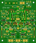
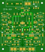
Some pictures to CFA-X mod1 simulation and schematic
I sim my cfa with your compensation style. Now, I know why nx-amplifier can have higher slew rate.
I have almost 3x slew rate with this compensation on my simple cfa, but THD get little worst.
Thank you BV.
I sim my cfa with your compensation style. Now, I know why nx-amplifier can have higher slew rate.
I have almost 3x slew rate with this compensation on my simple cfa, but THD get little worst.
Thank you BV.
Your amp would be perfect to learn which is more important to the sound... lower thd or higher SR. Can you listen and compare and give your impression of the sonic difference?
THx-RNMarsh
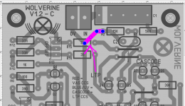
I built the CFA-XH V1.3 Mod1 that BV posted. On the pic of the board with modifications that I posted earlier, I missed the two new 10K resistors off of the collectors of Q1 & Q2. There are two more cuts that need to be made. I added the resistor under the board. I am attaching a revised picture. I tested the IPS but didn't have time to hook it up for a listen. Square waves look very clean and square. I will do more in the morning. Adding a pic just showing the trace cuts for clarity.
Blessings, Terry
Blessings, Terry
Attachments
I sim my cfa with your compensation style. Now, I know why nx-amplifier can have higher slew rate.
I have almost 3x slew rate with this compensation on my simple cfa, but THD get little worst.
Thank you BV.
I've "wrapped my head around" what BV's comp. does. By looping the
Cdom back to the input pair , the IP and the hawksford act "as one" ...
this is also more stable.
By summing the blockers (1Kuf) common mode cancellation is happening...
hence the greatly increased PSSR. The rail distortion is being cancelled.
I'm surprised this was not "discovered" in the CFA thread. This exceed's
floating the VAS on current mirrors or any other trick to bring a CFA
up to VFA standards. Including using CM's or cap multipliers ....
(the best trick yet)
I 've added some of his local decoupling ... single digit PPM is the rule @
100 V p-p . I'm quite impressed (for such simplicity).
OS
Your amp would be perfect to learn which is more important to the sound... lower thd or higher SR. Can you listen and compare and give your impression of the sonic difference?
THx-RNMarsh
Have you already hit these revelations ? And are waiting for us to
reach them (independently)?
OR , are you waiting for us to "get it right" ... so you can have a
better amp ?
Just curious ...
OS
- Home
- Amplifiers
- Solid State
- Slewmaster - CFA vs. VFA "Rumble"