Thanks for reply.Two resistors and two diodes, compared to schematic in #2861.But it not a must, it is only to ensure near perfect behavior at clipping.
Regards.
Thimios.
I had thought about using a pot there. I had to jump through hoops to come up with 60k and 40k. I am having issues trying to get this to run. I must have something wrong on my board. I'm not sure if anyone was able to look over the diagram I posted and tell me if they see any errors. Sounds like Thimios got it working on his boards but I can't tell by looking how he modified his to match your circuit. I will keep plugging away and see if I can get it to work.2 Terry
I attempt to trim DC ofset another way (IMO more comfortable) , look at attachments. Here is trimpot P1 added, to trim output DC ofset. Open potentiometer.zip file, put symbol file into LTC lib/sym/.. folder, and library file into LTC lib/sub/.. folder
In schematic are some changes (i hope last..) to improve behavior during clipping and at fast transients (to limit all internal currents to safe levels and avoid saturation under those conditions). Enjoy..But it is not "cook book"!
In th latest version, is there a reason why a 100k pot couldn't be used instead of the two 33k and one 47k pot?
Blessings, Terry
Last edited:
Safety.is there a reason why a 100k pot couldn't be used
Terry,After last modification, my board looks like bombarded but is absolutely functionable.I had thought about using a pot there. I had to jump through hoops to come up with 60k and 40k. I am having issues trying to get this to run. I must have something wrong on my board. I'm not sure if anyone was able to look over the diagram I posted and tell me if they see any errors. Sounds like Thimios got it working on his boards but I can't tell by looking how he modified his to match your circuit. I will keep plugging away and see if I can get it to work.
In th latest version, is there a reason why a 100k pot couldn't be used instead of the two 33k and one 47k pot?
Blessings, Terry
I can post some photos tomorrow.
Maybe 100k pot with 100k in series with wiper to ground will do also.. But better is to make both halves (+,-) independent, with wiper direct to ground.So then could the limiting resistor be between sweep and ground?
OS,
Wanted to confirm exact OPS locations you are talking about in post # 2907. Are you refereeing to R114,R115 and caps marked as CSB/CSA? AS you might tell I'm not that knowledgeable yet as Im not sure what you mean by R/C ... other than a filter ... but an RC filter located where ;-)
I've got 5 OPS boards from Jason and 5 of the CFA-XH as well.
I am planning on executing BV's latest Mods on the IPS...
I also recently ordered a Tek 475 just like Terry...and happen to have a HP 35665 FFT...I also have two of LC's first one modules.
I am reasonable in Eagle so if Jason is tied up I can attempt to rework boards as soon as we nail down the values using the hacked orinigal CFA-XH.
Anyway guys I'm open to suggestions on trying different BOM's on the OPSs...ie what will match against BV2's mods the best on the OPS.
Last item is suggestions on where to make OPS BOM posts...is this thread appropriate or would using Jasons Group buy thread better? We might want to keep this thread focused around IPS development...thoughts?
My Speakers are Tannoy Dimensions BTW for listening tests.
I will ultimately rework the CFA art around the BV modifications when the development cycle appears to stabilize. I do not like the idea of chasing rapid changes in the schematic, it is a fair bit of work to do.
Until then I'm sure the as-delivered CFA-XH will function just fine; we are after all chasing technical nirvana at this point.
Until then I'm sure the as-delivered CFA-XH will function just fine; we are after all chasing technical nirvana at this point.
Jason,
The thing that grabbed my attention on the BV mod is the improvement in psrr. That should be a significant improvement in s/n ratio and make it less important to need to chase a very low noise power supply, at least that is what I am thinking. That seems to be the major differential here between the CFA and most VFA amplifiers. I'm not to concerned with the improvement in the low frequency response that the VFA is supposed to have over the CFA. It also sounds like BV may have just addressed the reliability issue that OS brought up about the CFA vs VFA over years of use with his last tweak with his two resistors and diodes.
The thing that grabbed my attention on the BV mod is the improvement in psrr. That should be a significant improvement in s/n ratio and make it less important to need to chase a very low noise power supply, at least that is what I am thinking. That seems to be the major differential here between the CFA and most VFA amplifiers. I'm not to concerned with the improvement in the low frequency response that the VFA is supposed to have over the CFA. It also sounds like BV may have just addressed the reliability issue that OS brought up about the CFA vs VFA over years of use with his last tweak with his two resistors and diodes.
R114/115 + C110 -113 are the main driver/pre decoupling RC. Raising theseOS,
Wanted to confirm exact OPS locations you are talking about in post # 2907. Are you refereeing to R114,R115 and caps marked as CSB/CSA? AS you might tell I'm not that knowledgeable yet as Im not sure what you mean by R/C ... other than a filter ... but an RC filter located where ;-)
values to even 10R/68uf are easy and give 3-6db PSSR "out of the box".
The multipliers downstream will clean up any errata , You might lose another volt at the IPS ....
but the recommended slew series rail is 10V higher than a
"badger" or other mainstream class AB project.
CSa/CSb were to "cover my ar$e" in case of a unforseen EF3 stability issue.

To address "technical nirvana"(perhaps the wrong term) , my rework of the
spooky might be (nirvana = blown out/away).
Since it is not to be offered (yet) , it will be the "cleanest" , lowest thd
DIYA amp yet. Why not do it ? I intend to make it the ABSOLUTE forum
reference for a (sub) PPM IPS.
V1 is "good enough" @ 10ppm. H2/H3 is in the same ratio on both , why
do we need a 4X reduction in already low distortion ? I suppose it is
because it is there ...(or we can ?? )
OS
Jason,
Agreed no need to chase a new board layout at this time. I guess effort is better spent understanding and successfully implementing BV's mods at this point.
OS,
Thanks for the info...so a bit more resistance in R114/115 is going to mean a bit less slew and a bit of voltage drop from IPS...is that correct statement?
Also you stated best values in LTspice is seen at 15R and 47uF ... I take it you wouldn't straight up recommend this due to the trade off in voltage drop and slew?
PSRR improvement is always nice but I might rather have the slew and less voltage drop...is that correct thinking?
does the EF3 OPS plus CFA-XH work in a situations where you'd power each independently..? I have 500KVA Transformers that give 65V output...however could
I say run the IPS at a higher voltage without issue?
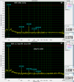
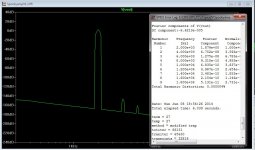
My experience with measurement vs listening is giving me some of the goal for an good sounding amp. Bellow example - very similar to CFA-X but with diamond input.
The thd numbers are not so very important bellow some level. I think the ratio between all the harmonicss and the imd products are important (maybe I am wrong ?).
Look at the few pics bellow and forgot a moment about the numbers, the harmonics spectrum is very similar to the other distortion producs so it must in some % describe the sound character of the amp. The is not playing sine waves but bit complex voltage curves.
Found also that good sounding amp should have the same THD character threw all audio band (without spikes and rising/lowering slopes, just smooth curves) and this is giving me the most of the problems, mostly at higher power levels.
The speed - is it a critical parameter ?? hmm........
The CFA-x imho will be a killer amp for the higher part of the audio spectrum.
So maybe it will be worth to make some of adjustmets in the other IPS versions even if the changes will cost a bit of the THD number and SR ??
Attachments
Jason,
Agreed no need to chase a new board layout at this time. I guess effort is better spent understanding and successfully implementing BV's mods at this point.
OS,
Thanks for the info...so a bit more resistance in R114/115 is going to mean a bit less slew and a bit of voltage drop from IPS...is that correct statement?
Also you stated best values in LTspice is seen at 15R and 47uF ... I take it you wouldn't straight up recommend this due to the trade off in voltage drop and slew?
PSRR improvement is always nice but I might rather have the slew and less voltage drop...is that correct thinking?
does the EF3 OPS plus CFA-XH work in a situations where you'd power each independently..? I have 500KVA Transformers that give 65V output...however could
I say run the IPS at a higher voltage without issue?
The OPS has two jumper locations which when removes gives you the ability to power the capacitance multiplier and therefore IPS from boosted rails.
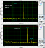
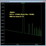
harmonic spectrum ??
I like that BG9 H2/3 balance !
I can't seem to get that with either CFA/VFA symmetrical's. So ...
try to eliminate both (below .6ppm/ 240v p-p). If you can get the H3 near -120db
does the ratio even matter anymore ?
The asymmetrical's (symasui/wolverine) already have the right ratio.
- they cancel odd harmonics.
Also , if this IS a factor (SQ wise) , going for single digit (or sub) PPM
might be a good idea for all these IPS's.
OS
My experience with measurement vs listening is giving me some of the goal for an good sounding amp. Bellow example - very similar to CFA-X but with diamond input.
The thd numbers are not so very important bellow some level. I think the ratio between all the harmonicss and the imd products are important (maybe I am wrong ?).
Look at the few pics bellow and forgot a moment about the numbers, the harmonics spectrum is very similar to the other distortion producs so it must in some % describe the sound character of the amp. The is not playing sine waves but bit complex voltage curves.
Found also that good sounding amp should have the same THD character threw all audio band (without spikes and rising/lowering slopes, just smooth curves) and this is giving me the most of the problems, mostly at higher power levels.
The speed - is it a critical parameter ?? hmm........
The CFA-x imho will be a killer amp for the higher part of the audio spectrum.
So maybe it will be worth to make some of adjustmets in the other IPS versions even if the changes will cost a bit of the THD number and SR ??
I like that BG9 H2/3 balance !
I can't seem to get that with either CFA/VFA symmetrical's. So ...
try to eliminate both (below .6ppm/ 240v p-p). If you can get the H3 near -120db
does the ratio even matter anymore ?
The asymmetrical's (symasui/wolverine) already have the right ratio.
- they cancel odd harmonics.
Also , if this IS a factor (SQ wise) , going for single digit (or sub) PPM
might be a good idea for all these IPS's.
OS
Attachments
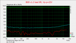
At PPB , It don't matter.
I think I might do some ground "rings" (shields) for this
layout.
(below) around the normal audio band / normal listening ...
It's quite distortionless . H2/3 would be meaningless (hidden in the noise).
Stays PPB until the OPS starts switching --> sub- PPM territory.
Dang ... run the spook on a class A OPS = distortionless amp.
PS - wolverine/badger can only bottom out at @ 1ppm class a only.
spook has the "upper hand".
OS
I think I might do some ground "rings" (shields) for this
layout.
(below) around the normal audio band / normal listening ...
It's quite distortionless . H2/3 would be meaningless (hidden in the noise).
Stays PPB until the OPS starts switching --> sub- PPM territory.
Dang ... run the spook on a class A OPS = distortionless amp
.PS - wolverine/badger can only bottom out at @ 1ppm class a only.
spook has the "upper hand".
OS
Attachments
Last edited:
Thanks Jason good to know. Are those the pads above R114/R115 ? That's the only thing that looks like a jumper to me.
You got it. Running one set of PSU rails the jumper is installed, running boosted IPS rails the jumper is not installed and the boosted supply soldered to the pads connected to R114 / R115.
Jason,
Agreed no need to chase a new board layout at this time. I guess effort is better spent understanding and successfully implementing BV's mods at this point.
OS,
... I take it you wouldn't straight up recommend this due to the trade off in voltage drop and slew?
PSRR improvement is always nice but I might rather have the slew and less voltage drop...is that correct thinking?
does the EF3 OPS plus CFA-XH work in a situations where you'd power each independently..? I have 500KVA Transformers that give 65V output...however could
I say run the IPS at a higher voltage without issue?
Slew is NOT affected , The only time you might get a V drop is with a VERY
heavy OP load. Even then , the multipliers would reduce this considerably.
The second option of the higher voltage auxiliary supply works VERY well.
I used this on my "supersym" modular , it gave me dual mono performance
with only one main PS.
A wire wrap terminal in the hole is how I attached my higher rails.
OS
- Home
- Amplifiers
- Solid State
- Slewmaster - CFA vs. VFA "Rumble"