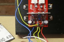
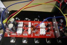
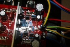
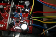
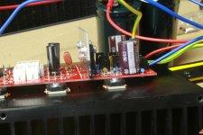
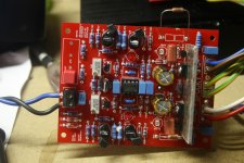
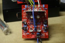
I tried to take some sharper pictures.
D102 is shorted.
D102 is shorted.
Attachments
-
 IMG_1043.JPG344.2 KB · Views: 540
 -
 IMG_1052.JPG316.7 KB · Views: 179
 -
 IMG_1051.JPG308.2 KB · Views: 162
 -
 IMG_1050.JPG276.8 KB · Views: 154
 -
 IMG_1049.JPG302.5 KB · Views: 133
 -
 IMG_1048.JPG304.5 KB · Views: 144
 -
 IMG_1047.JPG313.5 KB · Views: 445
 -
 IMG_1046.JPG327.3 KB · Views: 469
 -
 IMG_1045.JPG282 KB · Views: 477
 -
 IMG_1044.JPG383.3 KB · Views: 499
These are much better . Everything looks correct. Jason will likely be checking in soon. He's very good at spotting errors from a picture. When the board is powered up with 15 k resistors installed and the bias pot at 200 ohms, what is the voltage drop across R111, R112 and R113? What is the voltage between PD+ and ND-?
OK, so when testing the OPS with a 'dummy' IPS, such as a set of resistors from +V to PD and -V to ND we need to select the approximate value that yields about 5mA of current to ensure the bias generator becomes fully functional. Since your test supply is about +/-40V can you use a lower value than the 15K you have been trying please? We are looking to the 8K2 or there about value to get the required current. Then tell us what the minimum and maximum voltages are across PD-ND at the extremes of the bias adjustment.
OK, so the near-midpoint of the adjuster gives a bias spread that is in theory a little high to bias the triple. If you don't have any 8K2 can you series connect other common values to get you close, say 4K7 + 3K3?
I'm interested also in the available range of adjustment from minimum to maximum, reading the voltage from PD to ND.
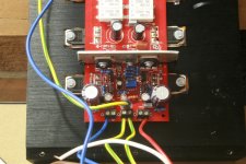
There may be something else going on, I will have to looks closely at your pictures to see if there's any clues there.
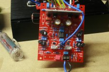
Edit: And there is! You should have used a 500R trimmer and you installed a 200R trimmer in the bias circuit on the OPS board. That will restrict your adjustment range and make it such that you can't get the bias low enough.
I'm interested also in the available range of adjustment from minimum to maximum, reading the voltage from PD to ND.
There may be something else going on, I will have to looks closely at your pictures to see if there's any clues there.
Edit: And there is! You should have used a 500R trimmer and you installed a 200R trimmer in the bias circuit on the OPS board. That will restrict your adjustment range and make it such that you can't get the bias low enough.
Last edited:
I put another 200r pot and a 47r resistor in series with the bias pot. Now I was able to start up the spooky ips and adjust the bias with the bulb limiter in place.
I tried playing some music through it, but the volume was very low. I have to turn the volume almost to max to get sound from my speaker.
I measured around 3.4v between nd and pd with the IPS connected. Is that normal?
I tried playing some music through it, but the volume was very low. I have to turn the volume almost to max to get sound from my speaker.
I measured around 3.4v between nd and pd with the IPS connected. Is that normal?
Eagle eye strikes again! I was mistaken on the correct pot value too.OK, so the near-midpoint of the adjuster gives a bias spread that is in theory a little high to bias the triple. If you don't have any 8K2 can you series connect other common values to get you close, say 4K7 + 3K3?
I'm interested also in the available range of adjustment from minimum to maximum, reading the voltage from PD to ND.
There may be something else going on, I will have to looks closely at your pictures to see if there's any clues there.
Edit: And there is! You should have used a 500R trimmer and you installed a 200R trimmer in the bias circuit on the OPS board. That will restrict your adjustment range and make it such that you can't get the bias low enough.
I put another 200r pot and a 47r resistor in series with the bias pot. Now I was able to start up the spooky ips and adjust the bias with the bulb limiter in place.
I tried playing some music through it, but the volume was very low. I have to turn the volume almost to max to get sound from my speaker.
I measured around 3.4v between nd and pd with the IPS connected. Is that normal?
The voltage difference between PD+ and ND- is controlled by the bias circuit and only effects the bias. PD+ and ND- change together in relation to V+ and V- rail voltage to create output. For example if you were to measure between PD+ and the positive rail you would see this voltage swing up and down with the audio signal.
3.4V sounds correct. The bias circuit needs to create enough voltage to slightly turn on 6 transistor junctions, The pre-drivers, the drivers, and the output devices.
I need to see voltage on a scope to figure out gain issues, so I won't be much help to you figuring this out. Jason has all these values memorized. Maybe start by double checking the values of R32 and R33. They are set your feedback voltage to the input.
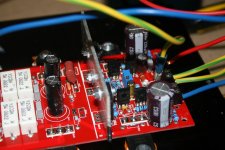
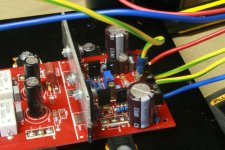
So, bias potentiometer bungle addressed temporarily with a permanent solution on its way. Now back to the low level / distortion issue. There are some IPS pics. I will look to see if anything pops up looking at those.
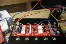
Can you post a picture of the IPS that is larger than the previously posted ones, preferably looking straight down on it? Thanks
Can you post a picture of the IPS that is larger than the previously posted ones, preferably looking straight down on it? Thanks
Last edited:
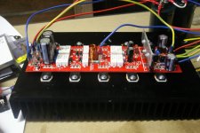
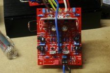
Here's some pictures. Let me know if you need any from other angles.
Attachments
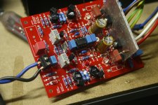
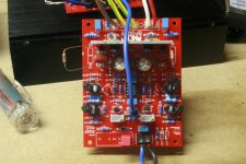
Thanks, those pictures are much better. I'll get a closer look at them.
Just in case you missed it in my prior comment, please verify C11 and C12 values. They look suspiciously small for being 2u2 film. As a sanity check you could simply pull the servo opamp. Spooky is normally well balanced and doesn't create large DC offsets without it.
Just in case you missed it in my prior comment, please verify C11 and C12 values. They look suspiciously small for being 2u2 film. As a sanity check you could simply pull the servo opamp. Spooky is normally well balanced and doesn't create large DC offsets without it.
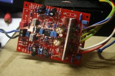
By the way, they are multilayer ceramics instead of film, does that matter?
I tried the other IPS board without servo and got 1.07v dc offset. Any ideas what causes this?
I noticed that I use ksa1381 and ksc3503 for q12 and q13 instead of MJE 350 and 340, is that fine or should I replace them with 340 and 350?
I tried the other IPS board without servo and got 1.07v dc offset. Any ideas what causes this?
I noticed that I use ksa1381 and ksc3503 for q12 and q13 instead of MJE 350 and 340, is that fine or should I replace them with 340 and 350?
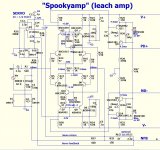
Here is the schematic you should be following. You have Q12 and Q13 correct.
DC offset without the servo in place is usually mismatched gain of input transistors. If you match the gain on Q1, Q2 Q5 and Q6 this should be closer to zero.
2SA1381 and 2SC3503 usually aren't available in the same gain ranks. If you look at yours you will likely see A1381- E and C3503-E. The E designates a higher gain on the device. This also causes some offset. Negative feedback and the servo both correct these offsets.
Attachments
Last edited:
The gain is higher with an E gain rank, but negative feedback takes care of it. Most of us run these devices with the mis-matched gain rank and have no issue.
These won't be causing any issue. DC offset with the servo removed isn't normally a concern either, as long as the servo is able to bring it down to an acceptable level, but it is something that is nice to have closer to zero.
These won't be causing any issue. DC offset with the servo removed isn't normally a concern either, as long as the servo is able to bring it down to an acceptable level, but it is something that is nice to have closer to zero.
- Home
- Amplifiers
- Solid State
- Slewmaster - CFA vs. VFA "Rumble"