I was actually amazed to see how Bonsai recommends particular mosfets for so many power supply voltage ranges... Is it really that important? I mean: why not take up to +/- 40V and some proposals for higher voltages. Or will smaller amps have better/quicker protection anyway? ")
For a regular First Watt, a good proposal would be the Infineon IPP042N03L, but will the IPP039N04L or the IPP015N04N be that much different? To be honest, I'm lost in the possibilities...
For a regular First Watt, a good proposal would be the Infineon IPP042N03L, but will the IPP039N04L or the IPP015N04N be that much different? To be honest, I'm lost in the possibilities...
Last edited:
I was thinking the same thing, but parallel or series? Bigger MOSFETS are quickly a much bigger load capacitance.. If you stay in the 'logic-level'-Mosfets, you might be better off with the extra drive-current instead of voltage... I'm just guessing.Actually, placing the two opticouplers in series and using one set of MOSFETS is also an option. That's what I did on my monoblocks. Should trip faster, twice as much voltage.
Berny,I was actually amazed to see how Bonsai recommends particular mosfets for so many power supply voltage ranges... Is it really that important? I mean: why not take up to +/- 40V and some proposals for higher voltages. Or will smaller amps have better/quicker protection anyway?
For a regular First Watt, a good proposal would be the Infineon IPP042N03L, but will the IPP039N04L or the IPP015N04N be that much different? To be honest, I'm lost in the possibilities...
I’ve offered many options for mosfets simply to make sure builders can have a wide choice. Availability has not been good on some devices so I’ve given builders lots of options. Just select the correct voltage from the table and then what you can afford or what you can get easily.
The mosfet gates are driven by the VOM127’s which have their LED’s wired in series. Since you are using logic level devices, you can do one of two things
1. Populate the board completely and then just wire the mosfet output pairs in parallel. This will give you half the output resistance in the switch
2. Populate only one output channel on the board, linking the unused VOM127 pins 1 and 2
Wiring the two VOM127 in series to drive the mosfets won’t really bring big benefits in this application since the switching speed is really controlled by the UPC1237 (it’s 100’s of us) and since you are using logic level mosfets, the Rds(on) will still be low (few milli-Ohms which is lower than the amplifier Zout)
Hi Andrew. Hope you are well. I posted on your Hifisonix site a couple of days ago. I have an Adcom GFA-5800 amp that I would like to modify to use your speaker protection board. See attached service manual with schematics. There are also many pictures on the internet of the internals of this amp. This amp is capable of very high current and puts out 400W/ch continuous into 4 ohms with 2.1dB of headroom. I plan on using one of the 70V rails to the MOSFETS as input to your board, and then the DC ground from one of the rail power supplies (not chassis ground). I will take the 120v AC sense directly off of the power switch. Can you offer any advise if my plan is correct? Also any advise on how to build a circuit for the current protection would be appreciated. I have no idea what current value I should target... or maybe I just don't use current protection.
Thanks,
Mike
Thanks,
Mike
Attachments
Hell, I just realised I never replied to you on this. Apologies - can I still help?No worries Andrew. No rush and I will be out of town until Monday anyway. Look forward to hearing from you and thank you in advance for your time.
Mike
Hello Eggburt/Harold,
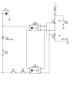
here is how to connect the Hifisonix Speaker Protection Board to your amplifier. As is without Rtrim (ie just the 270 Ohm resistor), it will definitely trip at 1.2 A output which is the 400W 4 Ohm load current for one pair of output devices. This might be a bit aggressive, in that case, connect a 10k pot where you see Rtrim, drive the amp to full power into 4 Ohms (or your minimum speaker load) and adjust the pot so the Speaker Protection Board trips. Remove the pot, measure the resistance, and then put the closest fixed resistor in the position of Rtrim.
Harold, this should work with your amp as well. Can you tell me the value of the emitter resistors and the 4 Ohm rated power?
Please see the Speaker Protection Board presentation for the resistor dropper values required to operate the board at voltages > 60V.
If you have any further questions, just let me know.
Last edited:
Bonsai, I'm not proficient at reading schematics, so perhaps you could tell me the value of the emitter resistors you're referring to in the attached schematic? As for the power into 4 ohms, it's rated at 325 W continuous power at any frequency between 20 Hz and 20kHz with both channels driven at < 0.04% THD. Thx!
Attachments
Harold, its the connection across TP201 and TO301 in your schematic - the emitter resistors are 0.22 Ohms each, total resistance is 0.44 Ohms for out purposes. I'll come back to you with the required resistors later today or tomorrow - got visitors at the minute.
Harold, at 325W into 4 Ohms, each output pair is delivering ~2.25A Amps into the load and generating 0.7V peak across said 0.22 Ohm degeneration resistors. I would use the circuit in the post to Eggburt above, but OMIT Rtrim and replace the 270 Ohm resistor with a 68 Ohm resistor initially. Drive the amp at full power into 4 Ohms and check it does not trip. If it does, use the same method in the post above to select Rtrim.
(Note in your amp, you have 4 pairs of output devices, so the peak currents are higher than Eggburt's amp and your emitter degen resistor is 0.22 ohms vs 1 Ohm for the source degn resistors in his amp)
(Note in your amp, you have 4 pairs of output devices, so the peak currents are higher than Eggburt's amp and your emitter degen resistor is 0.22 ohms vs 1 Ohm for the source degn resistors in his amp)
Last edited:
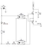
Eggburt, the post of mine above is incorrect, so let's do it again. The amp is 400W into 4 Ohms, so that is 10A RMS into the load at full power, 14A peak. With 8 pairs that is 1.75V peak across one of the emitter degen resistors (not both as I incorrectly stated in my earlier post). The opto emitter diode is typically 1.1V and we want 10 mA through that so (1.75V-1.1)/0.01 = 65 Ohms. Use 68 Ohms and adjust Rtrim per the earlier post.Hello Eggburt/Harold,
here is how to connect the Hifisonix Speaker Protection Board to your amplifier. As is without Rtrim (ie just the 270 Ohm resistor), it will definitely trip at 1.2 A output which is the 400W 4 Ohm load current for one pair of output devices. This might be a bit aggressive, in that case, connect a 10k pot where you see Rtrim, drive the amp to full power into 4 Ohms (or your minimum speaker load) and adjust the pot so the Speaker Protection Board trips. Remove the pot, measure the resistance, and then put the closest fixed resistor in the position of Rtrim.
Harold, this should work with your amp as well. Can you tell me the value of the emitter resistors and the 4 Ohm rated power?
Please see the Speaker Protection Board presentation for the resistor dropper values required to operate the board at voltages > 60V.
If you have any further questions, just let me know.
View attachment 1246599
- Home
- Amplifiers
- Solid State
- Speaker Protection Board