If you could curve trace that individual MOSFET taking into account the VDS (equals vin-vout in this case) to test at, and the junction temperature Tj in your particular set up, it would surely show the deviation parameters that make sense.
Making the basic VRset/Rset verification first when assembly is over with a light load resistor, shows the truth without all the above.
Tj in particular can play a big part when targeting over 400mA for an IRF9610. Beyond batch deviations etc. See how it can vary for 0.6A between extreme temp cases at -6V VGS as an example.
Thanks Salas; appreciate the insight.
Bummer, no go. LEDs don't light up still, and I measure 1.5v on the outputs. I do notice some voltage drop on the inputs, from 15 down to ~9 or so.
I'm just going to build another board, as I started this one a way back and only recently got back to it so maybe I messed something up along the way.
R101: 12ohm
R103: 2Kohm
R105: 1K trimmer
I'm just going to build another board, as I started this one a way back and only recently got back to it so maybe I messed something up along the way.
R101: 12ohm
R103: 2Kohm
R105: 1K trimmer
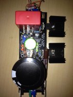
I didn't realize the unpopulated LEDs needed to be jumpered.
What resistor value should I select for the dummy load? I'm looking to simulate 90ma, am not quite making sense of the calculation.
I end up with 1.3k, but that seems way too high compared others. I think 30something Ohm seems more appropriate?
I'll try that tonight. Thanks!
Attachments
Bummer, no go. LEDs don't light up still, and I measure 1.5v on the outputs. I do notice some voltage drop on the inputs, from 15 down to ~9 or so.
I'm just going to build another board, as I started this one a way back and only recently got back to it so maybe I messed something up along the way.
R101: 12ohm
R103: 2Kohm
R105: 1K trimmer
If you start a new reg first to complete the pcb populate & check only the CCS, if OK continue to complete the rest of the board.
Hi, hopefully someone can point me in the right direction. Ive built 3 salas shunts v1.1, one BJT based for buffalo dac which works perfectly. The other two IRF base shunts not working as desired: looking for circa 290ma for legato IV inc. 100ma shunt @ 12-15v. Transformer is 2x15v 30va. Measured dc after shunt rectifier as ~20.5v] Both IRF have same problem - With 75R dummy load; V can be set to 12-15v seems ok but with real load; legato 3.1 IV stage, no red leds lit, output V drop to near 2v. Across R201/301 (8r2 /3w) measures 2.5v. So. Measuring the negative shunt current out to dummy load (75r) I get 144ma at 13v (too low to power the legato and hence no leds and V drop?) and also this rises with increase in V to 169ma at 14.5v. Can anything be concluded from this? I have also tested with CCS separated, shorted current out is 312ma 2r load 310ma 8r2 load 302ma 75r load 133ma
2.5V/8R2=305mA. That is their CCS. 312mA shorted measurement ties with that by only 2.3% experimental error. 20-30mA from that should go to the reg itself as a minimum.
If legato IV draws about 290mA then the regs are almost choked. Use 5.6R 3W-5W. Set Vo so to have 7V DCVin-Vout minimum. It helps the CCS rigidity.
If legato IV draws about 290mA then the regs are almost choked. Use 5.6R 3W-5W. Set Vo so to have 7V DCVin-Vout minimum. It helps the CCS rigidity.
Thanks for the reply Salas. Apologies - to be clearer in description: my legato requires +190ma and -205ma (based on twisted pear placid BP HD measurements). So 290ma output would allow 85-100ma of healthy shunt. Ive tried with 12v 13v 14v etc for output, it seems to not make much difference, except for increasing current with V !? With the load over a certain amount - I guess somewhere nearer to 75r, the current drops off below functioning output. 12V out should allow decent V drop from 20.5vdc in? but from measuring, it shows the lowest current (75r load 133ma).
Last edited:
Your dummy load uses, depending on voltage, 160-200mA per rail, and you say the regulator behaves properly with that load. The actual load is spec'ed at 190mA pos and 205mA neg, which is slightly unusual for the negative rail to draw more current. Have you tried dummy loads that more accurately mimic that expected actual load? That is, can the regulator drive a resistive load that draws >200mA? Can it do so at your target voltage range? How are mosfet temperatures when doing so? I would be especially interested in the negative supply, as I found I needed a much lower current setting resistor on the negative rail to get the same current, certainly lower than 8R2. To have a -15V regulated output at about 280mA I needed a current setting resistor close to 2R5.
If the regulator can drive a resistive load in excess of the expected load current, then you need to look at the circuit you are supplying. Could it be causing the regulator to oscillate? Again, what happens to device temperatures? Does the circuit you are driving actually draw that current? Can you supply it from a simple 3-terminal regulator to measure the current draw?
When you say "Measuring the negative shunt current out to dummy load (75r) I get 144ma at 13v", what current are you measuring exactly? (13 volts across 75 ohms means 173mA, so where are you measuring 144mA?)
I'm just trying to understand.
Salas, 270r for all gate resistors (from kit). I just measured all the resistors and they are working on spec.
nezbleu - I measured the current in series from output into the dummy (and also initially calculated from setting resistor V, measures 2.5v and 2.8v for the two psus). I have four green leds so my R would be a little higher maybe, 8R2 is what the latest Bib calc makes to get ~300ma with my measured leds.
I connected again to to legato and measured the current to it (in series at output) at 305ma, but with this the V drops off to 2.2v and red leds not lit. Connected to 75r dummy again red leds light, V is normal but measured output current drops to 177ma
Weird for sure
Last edited:
How much does the Vdrop across the Power Input to Power Output fall, when you start loading up the regulator?
It looks from your data that you have starved the input. The CCS cannot work if you don't have sufficient voltage at the currents you require.
I have said before and looks like I need to repeat it. Test the CSS first. Another member very recently suggested the same, he obviously remembers what I said.
Once you know that the CCS works properly, then when the voltage reg is added you can check back to see if the same voltage conditions still appear across the CCS.
I connected again to to legato and measured the current to it (in series at output) at 305ma, but with this the V drops off to 2.2v and red leds not lit. Connected to 75r dummy again red leds light, V is normal but measured output current drops to 177ma
Weird for sure
If the legato draws 305mA then you need to set the CCS higher than now. Decrease the reg's current setting resistor.
OK, so just measured the Input Vdc again, with 75r load and its dropped to 18.5v.
With 36r load Vdc in is 21.5v. Looks like the transformer does not have enough for this reg.. ?
In addition raising the Vout to max 19v into 75r dummy increases current to 260ma
With 36r load Vdc in is 21.5v. Looks like the transformer does not have enough for this reg.. ?
In addition raising the Vout to max 19v into 75r dummy increases current to 260ma
How much does the Vdrop across the Power Input to Power Output fall, when you start loading up the regulator?
It looks from your data that you have starved the input.
So what is the Vdrop across the CCS? For each of the test output currents?
That is the big clue to what is going on and going wrong.
Set the CCS to 10mA, then 30mA, then 100mA, then 300mA. For each measure the Vdrop.
Now attach you test load and set the Reg to work.
Is the Vdrop as expected? If the Vdrop has suddenly gone down you have identified your problem. You are starving the CCS.
I had one wired backwards. Replaced it, verified all the others light up in the right way, but still no go :*( . Getting same thing, no LEDs light up, and now getting a -1.5V at the outputs.
Could it be possible some component broke due to the LED oriented wrong?
I'm gonna build a 5V BJT version this weekend and see how that goes.
Thanks for the help guys.
Could it be possible some component broke due to the LED oriented wrong?
I'm gonna build a 5V BJT version this weekend and see how that goes.
Thanks for the help guys.
It can only be a wrong orientation for an LED or a dead one. I would check that each one can light up in the PCB noted direction with a 9V battery or a capable DMM in diode mode.
If you start a new reg first to complete the pcb populate & check only the CCS, if OK continue to complete the rest of the board.
Would you mind describing this process in more detail? What needs to be populated in order to test just the CCS? I've just been following the build guide.
Thanks,
-yammy
I had one wired backwards. Replaced it, verified all the others light up in the right way, but still no go :*( . Getting same thing, no LEDs light up, and now getting a -1.5V at the outputs.
Could it be possible some component broke due to the LED oriented wrong?
I'm gonna build a 5V BJT version this weekend and see how that goes.
Thanks for the help guys.
See the if BC transistor shows 0.6V between B,E leads. See if Mosfets show few Volts between outer leads G,S.
post the schematic you have chosen and we'll tell you the component numbers.Would you mind describing this process in more detail? What needs to be populated in order to test just the CCS? I've just been following the build guide.........
- Home
- Amplifiers
- Power Supplies
- SSLV1.1 builds & fairy tales