The Vref components should not be changing current with different test loads. Q103 is supposed to give their current. Something allows communication. Take those Q103 and Q105 out and make sure they test normally like working in an idss test. Also look for any solder bridge or blob in the board that shorts something.
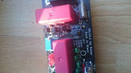
i tested them before putting them in, but i will try again... what is really wierd is that i looked again at the "pinout" of the 117gr and the pcb and now i am totally confused... it seems like drain and gate are connected together the way i mounted them ... could it be possible that the orientation suggested on the pcb is not right for this fet? attached a picture showing the way i mounted it.
edit - scratch that, mounted the right way, just got confused by what is what ;-)
edit - scratch that, mounted the right way, just got confused by what is what ;-)
Attachments
Last edited:
yay, looks like we are getting somewhere ... i replaced 303 and 305 and now i get 8,5vdc output with the trimpot at max ... doesn't make sense they mesaured ok, but whatever ;-)
I guess i replacing r103 with a 2k should get me to the 10V?") thanks so much for your patience
thanks so much for your patience
I guess i replacing r103 with a 2k should get me to the 10V?
thanks so much for your patience
Last edited:
I don't know maybe for spares. Small Leds are easy to overdo with the iron. Especially when reworking a board. That flat head type he had chosen is tighter for random Vf than various others nonetheless. The main impact of parts tolerances will be in how much CCS current someone gets vs what he may expect. Biggest contributor will be the MOSFET with its Vgs differing by sample. R101 can always be chosen differently to compensate for any gross off target result. In general when you target say 300mA and you end up with 285mA and 325mA in two channels when you have 100mA basic consumption from the load you don't care. Because you already have rich hot-rod that will cover any extra demand and that CCS difference will not make any interesting difference in the MOSFETs transconductance. Just always measure voltage drop across R101,(201,301) and divide by its value so to know what the CCS really runs when finishing a build so to have a picture.

Ok. Thanks.
I asked some posts back if i have to hotrod for the ba-3 preamp. If i am not making wrong deductions, and if the ba-3 is 50ma hungry per channel, the total is 100ma and if this is correct don't i need to have a 200ma margin? So, 300ma is the total that i need to have. Just thinking. If so, the 300ma value exceeds the 200ma in the manual for a normal use. That's why i asked if i have to use the Mur820 . This thinking could be totaly wrong if the 200ma spare current is too much.
I am sorry, i am really in the beggining of my learning curve and my function is not exponencial!
- Home
- Amplifiers
- Power Supplies
- SSLV1.1 builds & fairy tales