Plugged it in this evening.But once again, have you listened to it ?
Sounds very good so far. Only 2 minutes of listening but I would say it tends towards "warm".
So if I am understanding you correctly:With square wave input you have to look at the rise time on your scope that is from zero to the top of the scale where it flattens out. The frequency involved for rise time is in inverse proportion to this
Fortunately square wave is not representative of music what one has to consider is the rise time of the wave form as the nominal 1kHz is 1/t the same applies for 20k square wave. The instantaneous frequency on the vertical scale is much greater than 1kHz on the horizontal scale. It the output is low say 4V peak for 1W then the rise time will be lower than for say 20V peak for 25W.
There is another stability measure to apply know as settling time at the peak of the wave along the horizontal axis where the wave form should recover from any anomaly within a specified time of no more than 10 uS.
If you are seeking to drive your amplifier into low impedance loads at high volume levels, I noticed that Rod Elliott's Class A circuit was virtually the same as the present one with additional output transistor pairs. From other designs with similar output powers as yours I think that the safe operating area of a single pair of output devices is not sufficient for your intended use if my previous comment is true.
on the 1kHz square wave the time from the 0v cross to the peak of the square wave appears to be:
200us scale divided by 5 subdivisions = 40us per subdivision.
I count 33 pixels per subdivision: 33 pixels / 40us = 1.2 us per pixel.
From this I see the rise time on the positive going half of the 1khz square wave to be 2.4us from 0v to the 1.774v peak.
I don't quite follow what can be inferred from this? Slew rate?
The settling time is a bit hard to decipher due to the noise on the square wave trace. I've stared at it for a few minutes and its not obvious what is the settling of the overshoot versus the general noise.
Definitely not high volume listening under normal circumstances. My sleeping toddler would not approve of this.
Tomorrow night I will hook up my scope while at a typical listening volume and see what I actually listen at.
looking at pics in post 432, your input wiring seems very close to output wiring = oscillator
why no screened cable for input wiring?
why no screened cable for input wiring?
I will be using screened cable for the input wiring on the final build after painting/finishing.
Have you already installed the output coil?? It is the only way how to make FB amplifier stable with squares and capacitive load >= 150nF.
It is correct to say that it is the only way with most amplifiers. First Watt designs use no output coils, even for amplifiers with NFB (F5 in example).
My amplifier with 60-100 dB NFB happily drives 8.2 uF low ESR capacitor without any output coils.
My amplifier with 60-100 dB NFB happily drives 8.2 uF low ESR capacitor without any output coils.
Rise time is measured from 0 volts to the peak of the square wave on the horizontal time base. Slew rate is the voltage measured on vertical axis at 1us on the foregoing time basis.Plugged it in this evening.
Sounds very good so far. Only 2 minutes of listening but I would say it tends towards "warm". So in that circumstance the load is at the end of the speaker cable. It may be an encumbrance to try your square wave at this point but placement of the test resistor and parallel capacitor ignores the inductance in the cable. Rod Elliott included an output coil in the most recent previous incarnation but deleted this for the present circuit. If you must test near the output terminal put a 0.22R resistor in series with your square wave test load. The voltage drop across a resistor is more linear than that across any coil. You don't see any coils in the input to an audio amplifier.
Perfect. And most critical several nF range is fine as well.How about range 47nF - 220nF?
https://www.diyaudio.com/community/...-class-a-amplifier-my-way.404147/post-7474526
This design does not use an output coil.Have you already installed the output coil?? It is the only way how to make FB amplifier stable with squares and capacitive load >= 150nF.
It is true that is is spec'd without a coil. However, I recall reading somewhere on the site that Rod suggests it may benefit from a small coil if long speaker leads are used. Maybe try adding something like a 1u inductor to see if it helps?
8 to 10 turns of 18 gauge wire around something like a AA sized battery should give you around 1u.
8 to 10 turns of 18 gauge wire around something like a AA sized battery should give you around 1u.
Even 0.5uH may often help, in parallel with a resistor of several Ohms. In the past, I was also often designing without output coil, and it was a BIG mistake. Exactly what you have said, long speaker cables, especially coaxial. It is not about LF capacitance in audio band, but about transmission line input capacitance in MHz range (reflections), that may collide with UGF loopgain and kill the stability.
With the scope on the binding posts I am getting 0.2Vrms at my typical evening listening level.
I= E/R = 0.2/4 = 0.05A
P=EI = 0.01W
0.6Vrms is getting to loud for sleeping toddlers.
0.09W
This just proves whole point about the first watt....
I= E/R = 0.2/4 = 0.05A
P=EI = 0.01W
0.6Vrms is getting to loud for sleeping toddlers.
0.09W
This just proves whole point about the first watt....
In regards to shielded cable.
Which is the better option. 2 Core shielded cable with a hot and a ground wire and the shield connected at one end. Or single core with the shield acting as the ground?
Which is the better option. 2 Core shielded cable with a hot and a ground wire and the shield connected at one end. Or single core with the shield acting as the ground?
The cable I use is a braid and and foil shield type. The action of this is of passive filtering you can connect the braid to a solder tag at both ends and fix that by nut and bolt to your chassis. You can then follow normal wiring practice for hot and ground wiring.
G'day Guys,
I did a bit of testing on my old LM3886 power amp that this build is supposed to replace.
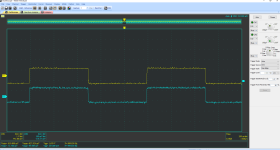
The square waves are much cleaner looking on this amplifier, I only went as far as a 4R load and established that the messy square waves I am getting from my P3A are due to the P3A and not the test equipment:


The sine waves look the same. Square waves are much nicer looking.
Here is the schematic for the LM3886 board:

I notice that the input filter is more aggressive.
I think the next step for me is to increase the value of C2.
I did a bit of testing on my old LM3886 power amp that this build is supposed to replace.
The square waves are much cleaner looking on this amplifier, I only went as far as a 4R load and established that the messy square waves I am getting from my P3A are due to the P3A and not the test equipment:


The sine waves look the same. Square waves are much nicer looking.
Here is the schematic for the LM3886 board:

I notice that the input filter is more aggressive.
I think the next step for me is to increase the value of C2.
My unit gives nice clean square waves upto 100 Khz. No coil on the output. The Zobel resistor did get hot.
I need to repeat the tests without the Zobel. (100nf and 8 ohm resistor). Its good that you compared another amp. I have had issues with the scope, my probes and with my body introducing signal measurement issues.
I need to repeat the tests without the Zobel. (100nf and 8 ohm resistor). Its good that you compared another amp. I have had issues with the scope, my probes and with my body introducing signal measurement issues.
The filter is a multi stage one with a higher roll off slope for frequency input. Normal single pole filters roll off at 6dB/Octave = a slope of 0.707. The one in your old LM3886 will have a higher rate of roll off that allows higher frequencies to pass without compromising stability. The square waves are better than you could expect with normal filtering because of the sophistication of the chip and the structure built around it. I like what I see in this as a model to work with - of course not possible with out re-designing your P3A.G'day Guys,
I did a bit of testing on my old LM3886 power amp that this build is supposed to replace.
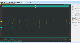
The square waves are much cleaner looking on this amplifier, I only went as far as a 4R load and established that the messy square waves I am getting from my P3A are due to the P3A and not the test equipment:
View attachment 1248155
View attachment 1248156
View attachment 1248157
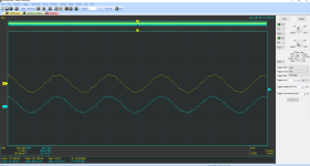
The sine waves look the same. Square waves are much nicer looking.
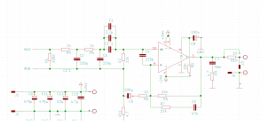
Here is the schematic for the LM3886 board:
View attachment 1248159
I notice that the input filter is more aggressive.
I think the next step for me is to increase the value of C2.
Your tests have been done in the raw without consideration of such items as a volume control and speaker cable. The former can add series resistance unless a low stage buffer stage is used at the input. I think Rod Elliott expected a higher impedance in series with the P3A input and some inductance in the speaker cable.
I have simulated the P3A with multiple parallel cap values and while this was stable in previous simulations as I believed to the sufficient given experience of others who have built this amplifier, I did not go so far as to test lower parallel capacitor values which I know will have higher resonance frequencies which will therefore be more challenging of circuit stability. I was prompted to check lower values by comments in post 465 by PMA which has substance.
There is no scope to modify your input low pass filter to emulate the LM3886 and I believe you are using a low output impedance buffer ahead of your input. In that case your only option is to increase the value of C2. You can solder some test values to tracks under your pcb however I think you will end up with a value of around 1nF. The other thing you could do is put your test load at the end of the length of speaker cable you intend to use and put your scope on the load attached to the far end. As there will be some inductance in this some ripple will be observed which is normal. If you then put the probe at the output of your amplifier you should see a clean square wave. Don't fret if this has some rounding.
I have previously suggested the inclusion of a 0.22 Ohm resistor instead of an output coil. I you try that you should see the same shape square wave at the near and far load end and the output of your amplifier. As for a coil I looked at some Supra low inductance cable to see what inductance that has, What you have will be different for inductance per metre and you should check the specification to see if you have enough.
I'm not at home until Friday if you let me know the result I will include it in my simulation and post the .asc file
Yes, that's himVipin if this is the same guy you sent me these boards.
You can see VASP is also selling the same. Im not keen to post his websites links as there maybe drama.
The above link the guy just gave away free PCBs. And his schematic and gerbers are also free.
He giveaway some PCBs, I was among those who got them, I sent you them because I already build my own handmade pcb at that point, so I thought you might find them useful,
Anyway there are other people who also selling this design like vasp,
I thought you find other designs too, so I asked
I have a P3A that was oscillating on the rise around 0V and fall just before the negative peak when I left the power transistor leads long. After clipping them, the (rather large) parasitic oscillations went away, but I shelved the amp for a while thinking it must be pretty marginal..original P3A
AM4 diff current too high 3.22 ma
feasible too high with no degen.
AM3 second Gain stage.
Marginal low current 5ma
Should be closer to 6 to 8ma
AM2 driver transistors
Marginal current 2.66ma could be closer to
3 or 4ma
VF1 DC offset 92 mV = bad
View attachment 1216735
Look familiar? = Ringing Oscillator
View attachment 1216747
Just removing C6 reduces the ringing, pretty much pointless part
causes more problems. Still not stable. So lets try to fix it
without redesigning the whole board and with just value changes
View attachment 1216752
To fix DC offset raise R7 to 820 ohms
lowers current from 3ma to 2ma and helps to stabilize the amp
since degen cant be added.
Lower bootstrap resistors R9/10 to 2.7k
Raises current from 5ma to 6ma.
This changed DC offset from 92mV to 15.8 mV
vast improvement.
Improved stability greatly.
100n needs to be added across T9
and removing C6 contributed the most
to actually stabilizing the amp.
C4 can possible be lowered to 68p to improve
high frequency slew rate.
If the the amp is still unstable add 1.8p across R5
Lower R12 and R11 to 150 ohms to increase driver current.
from 2.66mA to 3.66mA
This will help keep bias from being sky high or way at the end
of the pot travel. If bias still to high at way end of the pot
you can even go lower to 120 ohms
View attachment 1216760
No ringing, feasible DC offset
View attachment 1216767
My Adcom amplifier started making a buzzing sound (the amp itself, not heard through the speakers) yesterday, so I took that out and put my P3A on the bench.
I applied your changes except for the 1.8pF lead compensation cap. Ran the amp through some simple tests with an oscilloscope and my phone as an audio source. No signs of oscillation. Installed it in the living room. Sounds great.
Wish I could do some THD measurements but I don't have the equipment. Thanks for the tips.
- Home
- Amplifiers
- Solid State
- Stability testing my new Rod Elliot P3A