Drivers BD139/140 onsemi
Outputs 2SA1943/2SC5200 Fairchild.
You are right on the input sine wave. I hadn't paid it too much attention but it does look pretty nasty.
Outputs 2SA1943/2SC5200 Fairchild.
You are right on the input sine wave. I hadn't paid it too much attention but it does look pretty nasty.
make a foto of your connection of your fg(frequency generator)...be sure that GND is well connected.
generally: every bad connection and "reflection" are not goo to be amplified 😉
generally: every bad connection and "reflection" are not goo to be amplified 😉
With the input shorted and no load what are you seeing on the output with your CRO? Also use a multimeter (not your CRO) to check the DC offset.Drivers BD139/140 onsemi
Outputs 2SA1943/2SC5200 Fairchild.
You are right on the input sine wave. I hadn't paid it too much attention but it does look pretty nasty.
I'm suprised you found those output transistors. The Toshiba equivalents are cheaper and easier to locate.
Vipin if this is the same guy you sent me these boards.
You can see VASP is also selling the same. Im not keen to post his websites links as there maybe drama.
The above link the guy just gave away free PCBs. And his schematic and gerbers are also free.
The above link the guy just gave away free PCBs. And his schematic and gerbers are also free.
I use Mogami "Neglex" 2534 referred to as "Smog Lifters" in the defunct USA Audio Amateur magazine 3-4 decades ago. I don't know if it has an RG number to compare with RG 316 but it should not be hard to check this out on the net.yes
use for example RG 316 - cheap and big enough to solder.
There was a project in Silicon Chip magazine of December 2021 for a Blameless amplifier called the "Humming Bird" that followed Self's input network values.His argument is that the source impedance will not be zero. He suggests for an active source, it's 30R at best and likely more like 100R. So, the RC network has an effective R of 40 to 110 putting the corner somewhere in the 1.4 to 4 MHz range.
If you agree that a typical active source is around 100R, then this seems reasonable to me.
His designs place great emphasis on low noise. The input R is one of the leading contributors to noise, so if you can keep this down, it fulfills his objectives. He goes on to state that the highest value he uses is 47R to keep noise low. At 147R (47 + a 100 source) the 3db frequency gets much closer to 1MHz
I'm simply stating his arguments. I don't think there's a single right answer here. It depends on your priorities and if you know what your source impendence will be.
this is a modified version of original P3A, it uses diode strings instead of LED for current source reference which i don't like personally.Vipin if this is the same guy you sent me these boards.
You can see VASP is also selling the same. Im not keen to post his websites links as there maybe drama.
The above link the guy just gave away free PCBs. And his schematic and gerbers are also free.
@nano yes somebody gave a detailed explanation as to why LEDs work better on one of my posts. He quoted D Self.
I also mentioned this point on the youtube comments section of the above video.
Where I am stuck right now is figuring out a way to bench mark all these amps and ideas that I have.
Im used to building engines. Where its very simple. Put engine on dyno. Do work and put engine back on dyno. Use dyno to tweak and improve. Story over. Of Course most of the design is done in an engine simulator.
I need something similar for Audio. So I can test things like what happens if I change this part or value. I have been using engine simulation software for the past 20 years so I know the limitations with simulators. They help but for the final test you need noise floor and THD. Real world testing.
Walt Jung published an article in Audio Xpress magazine of April 2007 The green LED Digi-Key P309 performed a little better than two diodes with respect to rejection characteristics and impedance values. The article covered more involved constant current circuits but the LED does the job well enough.
Jung showed an example of CCS where the green LED was replaced by an LM336-2.5 voltage reference diode. I did see a simlator for this 3 pin part where R set was 1k. You could look at an SMD type for this. Good luck with your simulating this prospect. This diode has more precision as a voltage reference than a green LED if one is a aperfectionist.@nano yes somebody gave a detailed explanation as to why LEDs work better on one of my posts. He quoted D Self.
I also mentioned this point on the youtube comments section of the above video.
Where I am stuck right now is figuring out a way to bench mark all these amps and ideas that I have.
Im used to building engines. Where its very simple. Put engine on dyno. Do work and put engine back on dyno. Use dyno to tweak and improve. Story over. Of Course most of the design is done in an engine simulator.
I need something similar for Audio. So I can test things like what happens if I change this part or value. I have been using engine simulation software for the past 20 years so I know the limitations with simulators. They help but for the final test you need noise floor and THD. Real world testing.
Last edited:
This evening, I should have time to do some more tests.
First cab of the rank will be to try using my computer as the signal generator.
Sine wave straight out of my dac via RCA and see if this changes anything.
I am also bidding on a better scope which at this rate I should get rather cheap which is much higher quality and most importantly with higher quality probes as there has been some suggestion in the thread that my scope/probes are part of the problem.
G'day Guys,
Last night went well. By using my usual stereo system as the sig gen. My sine waves now look much cleaner.
I used a 1kHz/10kHz sine wave as a .wav file. Using the volume control in FooBar to get the signal to the normal level I test at.
RCA cable was used straight from the output of my dac directly into the amplifier.
4R
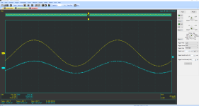
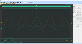
4R + 47nF
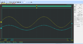
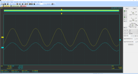
4R + 470nF
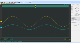
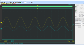
4R + 2.2uF
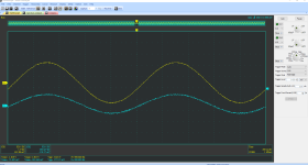
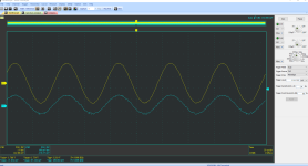
Not only is the sine wave looking clean but it is looking stable with up to 2.2uF in parallel with a 4R load.
All going to plan, tonight I will try some more square wave testing with capacitive loads.
Last night went well. By using my usual stereo system as the sig gen. My sine waves now look much cleaner.
I used a 1kHz/10kHz sine wave as a .wav file. Using the volume control in FooBar to get the signal to the normal level I test at.
RCA cable was used straight from the output of my dac directly into the amplifier.
4R


4R + 47nF


4R + 470nF


4R + 2.2uF


Not only is the sine wave looking clean but it is looking stable with up to 2.2uF in parallel with a 4R load.
All going to plan, tonight I will try some more square wave testing with capacitive loads.
G'day Guys,
I've been doing some square wave testing.
My conclusion is that the amp is unstable producing squares waves into a load of 4R and greater than 100nF of capacitance in parallel.
4R + 47nF
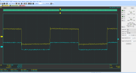
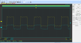
A little bit of overshoot but it recovers quickly.
4R + 100nF
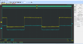
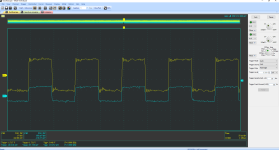
Same thing, a bit of overshoot but it recovers immediately.
4R + 150nF
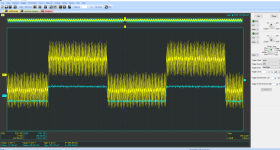
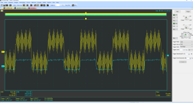
Oscillation!
The peak voltage of the oscillation gets worse as I increase the capacitance.
So the question is: What is an acceptable margin for capacitive loaded square wave testing?
Given that the amp had no issues with 4R + 2.2uF on sine waves.
I would think that square waves into 4R + 100nF is a pretty tough test to pass.
It seems to me like I can call this amp stable and continue on with finishing the build.
However I am just an idiot on the internet so I ask the members with more knowledge, experience and wisdom than myself: Is this an acceptable margin of stability?
I've been doing some square wave testing.
My conclusion is that the amp is unstable producing squares waves into a load of 4R and greater than 100nF of capacitance in parallel.
4R + 47nF


A little bit of overshoot but it recovers quickly.
4R + 100nF


Same thing, a bit of overshoot but it recovers immediately.
4R + 150nF


Oscillation!
The peak voltage of the oscillation gets worse as I increase the capacitance.
So the question is: What is an acceptable margin for capacitive loaded square wave testing?
Given that the amp had no issues with 4R + 2.2uF on sine waves.
I would think that square waves into 4R + 100nF is a pretty tough test to pass.
It seems to me like I can call this amp stable and continue on with finishing the build.
However I am just an idiot on the internet so I ask the members with more knowledge, experience and wisdom than myself: Is this an acceptable margin of stability?
My conclusion is that the amp is unstable producing squares waves into a load of 4R and greater than 100nF of capacitance in parallel.
4R + 47nF
It seems to me like I can call this amp stable and continue on with finishing the build.
it is not stable.
attached is a thread with scope shots regarding stability tests.
https://www.diyaudio.com/community/threads/xy-lm3886-kit-review-measurements.294032/
have you checked out your setup by testing another amp?
With square wave input you have to look at the rise time on your scope that is from zero to the top of the scale where it flattens out. The frequency involved for rise time is in inverse proportion to thisG'day Guys,
I've been doing some square wave testing.
My conclusion is that the amp is unstable producing squares waves into a load of 4R and greater than 100nF of capacitance in parallel.
4R + 47nF
View attachment 1245675View attachment 1245676
A little bit of overshoot but it recovers quickly.
4R + 100nF
View attachment 1245677View attachment 1245678
Same thing, a bit of overshoot but it recovers immediately.
4R + 150nF
View attachment 1245679View attachment 1245680
Oscillation!
The peak voltage of the oscillation gets worse as I increase the capacitance.
So the question is: What is an acceptable margin for capacitive loaded square wave testing?
Given that the amp had no issues with 4R + 2.2uF on sine waves.
I would think that square waves into 4R + 100nF is a pretty tough test to pass.
It seems to me like I can call this amp stable and continue on with finishing the build.
However I am just an idiot on the internet so I ask the members with more knowledge, experience and wisdom than myself: Is this an acceptable margin of stability?
Fortunately square wave is not representative of music what one has to consider is the rise time of the wave form as the nominal 1kHz is 1/t the same applies for 20k square wave. The instantaneous frequency on the vertical scale is much greater than 1kHz on the horizontal scale. It the output is low say 4V peak for 1W then the rise time will be lower than for say 20V peak for 25W.G'day Guys,
I've been doing some square wave testing.
My conclusion is that the amp is unstable producing squares waves into a load of 4R and greater than 100nF of capacitance in parallel.
4R + 47nF
View attachment 1245675View attachment 1245676
A little bit of overshoot but it recovers quickly.
4R + 100nF
View attachment 1245677View attachment 1245678
Same thing, a bit of overshoot but it recovers immediately.
4R + 150nF
View attachment 1245679View attachment 1245680
Oscillation!
The peak voltage of the oscillation gets worse as I increase the capacitance.
So the question is: What is an acceptable margin for capacitive loaded square wave testing?
Given that the amp had no issues with 4R + 2.2uF on sine waves.
I would think that square waves into 4R + 100nF is a pretty tough test to pass.
It seems to me like I can call this amp stable and continue on with finishing the build.
However I am just an idiot on the internet so I ask the members with more knowledge, experience and wisdom than myself: Is this an acceptable margin of stability?
There is another stability measure to apply know as settling time at the peak of the wave along the horizontal axis where the wave form should recover from any anomaly within a specified time of no more than 10 uS.
If you are seeking to drive your amplifier into low impedance loads at high volume levels, I noticed that Rod Elliott's Class A circuit was virtually the same as the present one with additional output transistor pairs. From other designs with similar output powers as yours I think that the safe operating area of a single pair of output devices is not sufficient for your intended use if my previous comment is true.
- Home
- Amplifiers
- Solid State
- Stability testing my new Rod Elliot P3A