I changed the vin to 1v and the freq to 10khz.
And this is what I got very high THD off 6%
Im just trying to see if the 70 watts output is possible on 35 volt rails with 1 volt peak to peak as per original design of Rods.

And this is what I got very high THD off 6%
Im just trying to see if the 70 watts output is possible on 35 volt rails with 1 volt peak to peak as per original design of Rods.
Rod Elliott designed this for 60 W r.m.s into 8R.
The peak output voltage is the square root of these figures multplied by root 2. As this peak in one direction this needs to be doubled for supply rail voltage values.
The calculations so far do not include voltage drops across the output transistors and allowance has to be made for this in designing an adequate power supply.
For professional use that will be much more substantial than for domestic use. Therein a question of tollerable sound level of going with various music genres for family and neighbours should be considered.
All you may need is sufficient current to handle peak transients. If full r.m.s power is not needed all the time a smaller transformer may suffice especially if space in your chassis for a larger transformer and supply capacitors is going to dominate the available space.
I suggest running the simulation to a point where THD does not is level across a board of peak voltage levels before these ramp up and live with that as a maximum power rating.
The second amplifier I built from a magazine project was rated at 40 W.rms this ran off 35 volt rails and the transformer centre tapped with 25 0 25 secondary winding pair was rated at 100 v.a. The magazine was Electronics Australia and the project name was Playmaster twin 40.
Last edited:
To measure distortion at 10kHz you cannot use the script for measuring 1kHz distortion. I don't have that for 10kHz you can find how to change that by looking a Mooly's tutorial on setting up and using LT Spice on this site.I changed the vin to 1v and the freq to 10khz.
And this is what I got very high THD off 6%
Im just trying to see if the 70 watts output is possible on 35 volt rails with 1 volt peak to peak as per original design of Rods.
View attachment 1237949
I have like 40,000 Uf caps and a 12 AMP transformer. So its not a power issue.
My uneducated guess as to why the woodstock is giving me 16 volts RMS on a 18-018 (5A) transformer is that it has more amplification stages.
So to figure out whats going wrong with the P3A I need to measure and tweak what stages he has used.
I have zero exp with Spice. So its a steep learning curve. But Im persistent if nothing else.
You mean wrong with your P3A. The original does not require tweaking.So to figure out whats going wrong with the P3A I need to measure and tweak what stages he has used.
To measure distortion at 10kHz you cannot use the script for measuring 1kHz distortion. I don't have that for 10kHz you can find how to change that by looking a Mooly's tutorial on setting up and using LT Spice on this site.
Here is how I run sims. Several others on this forum do it in a similar way. It uses parameters for amplitude and frequency that adjust the settings to produce the THD and FFT data.
For the max_fft_pts param, I use pwr(2,14) when adjusting the sim (runs faster), and then increase to pwr(2,18) if I want a better FFT plot. If you want the FFT floor slope to settle, you'll need to replace the electrolytic caps with voltage sources. Or run the sim for a VERY long time (by increasing the delaycycles). Mooly discusses this in the LTSpice How To thread.
This also include estimated junction temps for the semi's with a param to run it hot or cold. You can use this to see how offset and bias are affected by temp. You can also use the step function on the supply voltage to see how voltage fluctuations affect the sim.
Attachments
If I understand well, you are redesigning a perfectly functional schematics to fit an ill-fated pcb? 🤔Right thought the components and transformer are identical the PCB is not.
You MUST use output coil in this design.Here is how I run sims. Several others on this forum do it in a similar way. It uses parameters for amplitude and frequency that adjust the settings to produce the THD and FFT data.
For the max_fft_pts param, I use pwr(2,14) when adjusting the sim (runs faster), and then increase to pwr(2,18) if I want a better FFT plot. If you want the FFT floor slope to settle, you'll need to replace the electrolytic caps with voltage sources. Or run the sim for a VERY long time (by increasing the delaycycles). Mooly discusses this in the LTSpice How To thread.
This also include estimated junction temps for the semi's with a param to run it hot or cold. You can use this to see how offset and bias are affected by temp. You can also use the step function on the supply voltage to see how voltage fluctuations affect the sim.
I'm showing the schematic as designed on the ESP website. With the exception of small the VBE cap discussed on this thread. On Rod's site, his pages on "Power Amplifier Design Guidelines" specifically states that the P3A "hates inductors".
However, it you read these pages, you can see that he goes back and forth on whether the design can benefit from it. But, this current design has been in use for decades in this fashion, so to say it MUST use an inductor is simply not true.
However, it you read these pages, you can see that he goes back and forth on whether the design can benefit from it. But, this current design has been in use for decades in this fashion, so to say it MUST use an inductor is simply not true.
With your present set will not provide 35 -0-35 supply rails. specified by Rod Elliott.. You have to multiply your transformer RMS by 1.414 to get to that level. There also will be a little voltage loss due to the bridge rectifier affecting the final result.I have like 40,000 Uf caps and a 12 AMP transformer. So its not a power issue.
My uneducated guess as to why the woodstock is giving me 16 volts RMS on a 18-018 (5A) transformer is that it has more amplification stages.
So to figure out whats going wrong with the P3A I need to measure and tweak what stages he has used.
I have zero exp with Spice. So its a steep learning curve. But Im persistent if nothing else.
The VA rating of the transformer and a.c. voltage regulation % specifications need to be considered also. As I mentioned a 100 VA 25-0-25 a.c. transformer would allow 40 W RMS output into 8R albeit the peak voltage could be somewhat higher. A lot of mlleage from this was gained by advertising peak power outputs in the past.
This trend has been surpassed by advertisements for high output current delivery. where higher and physically larger transformers with higher VA ratings have become popular. If you take that route a 300 VA toroid will have a diameter of 120 m.m. You hould get good current delivery from this and low supply impedance without using 40,000uF supply caps taking up a major chunk of space in your chassis with a lower VA transformer.
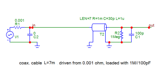
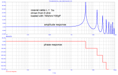
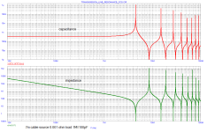
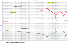
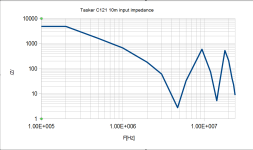
There is no circuit design reason for the amp to “hate output inductors”. Have you tried a range of capacitive loads 1nF - 1uF? Is it stable? It is important not only for the reason of cable simple capacitance, but, at high frequencies above 1MHz the cable driven from low impedance (amp output) and almost open at the other end (speaker inductance) has impedance that resembles a comb profile, with capacitance maxima in uF order, this may drive some amplifiers crazy resulting in unexplainable failures.However, it you read these pages, you can see that he goes back and forth on whether the design can benefit from it. But, this current design has been in use for decades in this fashion, so to say it MUST use an inductor is simply not true
I have done no testing and don't plan to. The circuit, ESP PCB and recommended BOM have been out for decades. It is a popular design with countless threads on it. Are you suggesting the countless builds of this design are all defective? If you follow the threads, nearly all problems are due to different PCBs or parts that are not on the recommended BOM (or are fakes).
If you deviate from the recommended BOM, use a different PCB or are driving an exotic load, then yes I could see the need to test. I am not in this situation.
If you deviate from the recommended BOM, use a different PCB or are driving an exotic load, then yes I could see the need to test. I am not in this situation.
I note that Rod Elliot suggested the same thing about C2 value of 1n - this being so despite the value shown in post 1. This is shown in the link you provided in post 411. You might like to compare what he said, in this link with my comment about reducing the value of C5 to improve slew rates if 30MHz output transistors were used. C5 at 100pf is a universal value to cover 4MHz devices where phase will reach - 180 degrees before the gain would reach unity. At that point oscillation would occur with these 4MHz devices.What is the rational for increasing C2 to 1nF? This drops the input pole from 1.59MHz to 159KHz. Lower still if the source impedance is high. If the objective of this is to block high frequency interference, then it seems to already be adequate at its original value.
Note also he mentions emitter swamping in his commentry, a term I have also used. I had not read the linked document before but I agree with the thrust in the content.
Last edited:
Most simulation end at the amplifier output terminals. Knowing that cable has levels of capacitance per metre has a bearing on results. My low inductance cable, by Supra has 0.15uH of inductance per metre. A reasonable length say 2.5 metres, is 0.37-38uH.There is no circuit design reason for the amp to “hate output inductors”. Have you tried a range of capacitive loads 1nF - 1uF? Is it stable? It is important not only for the reason of cable simple capacitance, but, at high frequencies above 1MHz the cable driven from low impedance (amp output) and almost open at the other end (speaker inductance) has impedance that resembles a comb profile, with capacitance maxima in uF order, this may drive some amplifiers crazy resulting in unexplainable failures.
I simulated this in Spice on the previous page in post 396 showing 10kHz square wave with cable inductance in series with the load of 8R//2uF.
I have not drawn up a Tian plot simulation.
Sorry about the confusion. Was comparing two different amps. One is a wood stock. With a 18-0-18 transformer. This gives me 17 volts RMS on the scope. (Testing is I keep increasing the input voltage till I see clipping and then measure the output voltage in RMS on a scope. Under 8 ohm load). The wood stock is a Quasi complementary.With your present set will not provide 35 -0-35 supply rails. specified by Rod Elliott.. You have to multiply your transformer RMS by 1.414 to get to that level. There also will be a little voltage loss due to the bridge rectifier affecting the final result.
The other setup is my Rod Elliot Clone. Here Im talking pure rail voltage. which is 35 volts d/c. Its actually a 8kg huge transformer. Built to 15 Amps spec but being locally built I think its closer to 12 amps. I plan to bi amp multiple amps off it eventually. It was built as a 28-0-28 transformer. Hope this clears up the confusion.
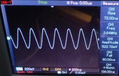
On this setup I setup a 1v peak to peak signal and my output out the P3A clone was only 9-10 volts RMS. On the scope.
I need to push the input to clipping and see what the final output in RMS on a 8 ohm load is.
I also need to setup REW / Arta / True RTA. To measure THD and Noise.
As testing THD and Noise on the scope seems to be a waste of time.
The amp works fine sounds amazing. Handles square waves all the way to 100 Khz clean.
Ive tested with various transistors from Toshiba to CDIL. To a few others. All work flawlessly.
Ive been swamped with work. And this is just a hobby thing so its not getting the kind of time Id like to give it.
Na I just buy what ever is being sold in my countries market. Importing stuff is a nightmare.If I understand well, you are redesigning a perfectly functional schematics to fit an ill-fated pcb? 🤔
And its working amazing. The THD and Noise numbers are amazing. My only doubt is the output. I guess my Input signal is lacking. As soon as I can will re-test everything but this time with a higher input voltage. Confusion is do you measure the input and then hook it up to the amp. Or do you hook it up to the amp and then measure. Cause not hooked up I get 1 V peak to peak from my Phone jack. When hooked up this drops to .2 volts
My plan is to share the THD and noise numbers shortly. I know they will be good cause the scope even with its crude FFT shows its pretty good. But I want to test it on REW.
This is just a hobby with me trying to recreate an amp my dad owned in 79. I have just purchased every PCB made in my country and built up a collection of AMPs. Which I will audition for my dad for him to pick.Whats left over I will use in my workshop.
Last edited:
I note that Rod Elliot suggested the same thing about C2 value of 1n - this being so despite the value shown in post 1. This is shown in the link you provided in post 411.
The article goes on to state "although this will be affected by the output impedance of the preceding stage". This is a big part of the problem if you are specifying a design where the output impedance of the previous stage is unknown. If the source is a active preamp, the output impedance is probably 200R or less. But it it's a passive volume pot, for example a 10K pot, then the max output impedance is 2.5k. This in series with the 1K R1 is 3.5K for a 3dB frequency of 43kHz. It gets much worst if a 20K or 100K pot is used.
Douglas Self discussed this in chapter 27 (Power Amplifier Input Systems) of his Amp Design book. If you look at his designs, he uses the opposite approach to Rod and places the pole frequency very high. He has the input filter at 10R and 1n for a 3dB frequency of 15.9MHz. This is to reduce input noise and account for high source impedances. If his blamelesss designs, he puts the pole even higher with 10R and 100p.
So, I guess it come down to what's important to you. Rod's primary interest is to guard against RF interference. Self is interested in low noise and guarding against rolloff in the audio range from a high source impendence. This makes sense considering their intended audience. Self is marketing primarily to commercial designs where specs matter. Rod is marketing to DIYers, and wants to have builders with limited experience have success.
So... If you know your environment and source, you can really tailor to your situation and your goals. Otherwise, it seems like there many different opinions on what is "correct" (like most topics in DIY audio).
- Home
- Amplifiers
- Solid State
- Stability testing my new Rod Elliot P3A

