SR20
Greetings
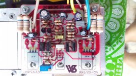
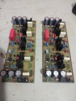
I have made sr20 with non darlington c5198 and 1941 it sounds ok. No turn on ploop, offset is ok bias 1.65 volt on ce while 65mv on 0r34.
Suggestions and comments are apreciated
Thanks
Sam
Greetings
I have made sr20 with non darlington c5198 and 1941 it sounds ok. No turn on ploop, offset is ok bias 1.65 volt on ce while 65mv on 0r34.
Suggestions and comments are apreciated
Thanks
Sam
Attachments
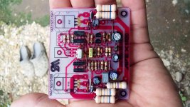
there are quite a few layouts of this amplifier...
Hello sir .I wana make this sr 200 10 pair .can any 1 help me
Greetings
I have made sr20 with non darlington c5198 and 1941 it sounds ok. No turn on ploop, offset is ok bias 1.65 volt on ce while 65mv on 0r34.
Suggestions and comments are apreciated
Thanks
Sam
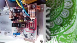
What is DC operating volts, I am play this on +/-40 volts. I think 40volts little high for that cute amp. What u think Sam.
Hello sir .I wana make this sr 200 10 pair .can any 1 help me
10 pairs ?🙄🤔
What is DC operating volts, I am play this on +/-40 volts. I think 40volts little high for that cute amp. What u think Sam.
Hi GPS,
congrats on successful build. +/-40V is ok for 8 ohm, little high for 4 ohm.
You could check heatsink temperature. I like to run it cooler than 50-55 Deg. C.
10 pairs ?🙄🤔
Ty for replying gps. I wanna run this on 10 pair left and 10 right
What is DC operating volts, I am play this on +/-40 volts. I think 40volts little high for that cute amp. What u think Sam.
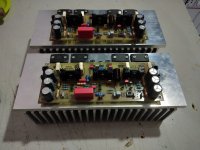
i tried it on +/-30 LV of my HX11 with 4r load during test
x2 of this can run together with my HX11(sub) for 2.1 audio.
my plan was to run with +/-30Vdc since i have plenty of 4700u 35v caps
for full power about 10-15vac on output about 60deg on 2pcs CPU heatsink joint together but for stereo i will add slow CPU fan.
i think 4-5 pairs on SR200 is max or run it in TEF mode for more outputs. but i cannot help you coz i am not a pro just hobbyist.
thanks.
Hi GPS,
congrats on successful build. +/-40V is ok for 8 ohm, little high for 4 ohm.
You could check heatsink temperature. I like to run it cooler than 50-55 Deg. C.
Prasi and Sam thanks for confirmation on SR20. Once again I'm thinking of making this Amplifier. My Last board burn with wrong connection by my mistake. I use SR20 in homemade sound bar.i tried it on +/-30 LV of my HX11 with 4r load during test
x2 of this can run together with my HX11(sub) for 2.1 audio.
my plan was to run with +/-30Vdc since i have plenty of 4700u 35v caps
for full power about 10-15vac on output about 60deg on 2pcs CPU heatsink joint together but for stereo i will add slow CPU fan.
i think 4-5 pairs on SR200 is max or run it in TEF mode for more outputs. but i cannot help you coz i am not a pro just hobbyist.
thanks.
Sam never think about to make SR200. I just wondered on sunny he want make with 10 pairs.
Regard
I use SR20 in homemade sound bar.
Regard
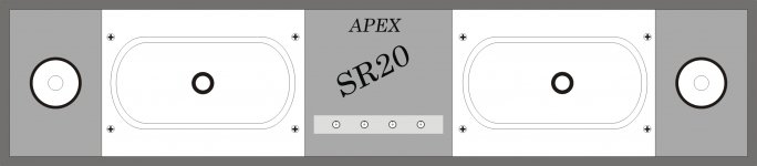
New sound bar idea😊
Attachments
nice... those are car speaker drivers?
Hello Prasi, Actually I have 4pc. 55 x 120mm woofer cone speakers with 8ohm 20w. So I plan to use these speakers in the sound bar. Last time I use these speakers with SR20. Blue circle is tweeters in last Bar's picture. Any suggestions please may be if I done any mistake.
Regards
Gurpreet
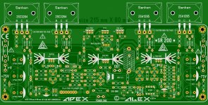
.....another PCB for Sankens , have split Q7 from Q8 ....")
and I need to check somebody if it's OK , and then I will post layout in black and white and the rest of files .
Regards ,Alex
Hi Sir,
First of all thank you for your contribution to DIY community. I want to try making your SR200 Amplifier with sanken transistors. I have most of the components with me to make this amplifier. Can you post the layout in black and white for making PCB's by Toner transfer method or the Gerbers.(Gerbers would be great) I will try toner transfer first if not successful i will get it made by PCB manufacturer.
Regards,
Sadik

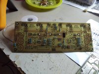
One of my friend helped me for getting the itched boards. I need help so asking for suggestion, Can I use 2.2uf /400V caps instead of 2.2uf /100v caps, I am unable to get the 100v rating locally. I will be using 40-0-40Vac / 600 Va transformer. I am attaching herewith the photos of my PCBs. I am just checking the fitment of transistors on heat sink so insulator is not used between the transistors and heat sink.
Attachments
Higher voltage capacitor is functionally acceptable, but can be physically larger. Just check it fits in the PCB footprint.
Pops.
Thankyou Sir
Today I powered on the PCB. It is working, but i am unable to set the Bais Voltage which is 20mv Across the 0.33/5watt resistors. I turn the trimmer ACW / CW (full both sides) but the bias voltage is not changing. The voltage across the 0.33/5W resistor i am getting is just 4 mV due to which the sound is not clear.
I am attaching the PCB which i am having.
I am attaching the PCB which i am having.
Attachments
- Home
- Amplifiers
- Solid State
- Studio Reference Amplifier