OK, that explains why you can't set the bias.
The VAS current is way too low. According to your measurement, you've got 0.091V/0.1K=0.91mA
Taking in account, around 1mA goes away through the diodes, you've got nothing left to drive the OPS. Correct voltage over R26, R28 would be some 0.6-0.7V (almost 10 times higher than you have now.
One more point - the fact the bulb starts glowing as soon as you connect the load tells me the amp starts oscillating with the load. But that may be caused by the issue mentioned above - too low VAS current and as a result no bias in the OPS.
Do you have an oscilloscope?
Thank you Sir for taking your precious time in helping me out. Basically i am expert in building Speaker Enclosures, so i have many power tools collection related to my hobby. I am not expert in amplifier building hence i do not have these tools. I want to make this amplifier as a reference amplifier to test all my speaker builds.
To start troubleshooting, I recommend to measure the voltages across the following resistors (with no load, no signal):
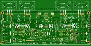
R11 - 15 K - Measured Voltage : 15.29 VDC
R16 - 3.3 K - Measured Voltage : 0 Volts
R17 - 3.3 K - Measured Voltage : 0.905 VDC
The Values are mentioned in RED in above quote. I am also attaching the image in which i have mentioned the values for better clarity. Additional to above I am feeding this amplifier with 40-0-40 VDC. I am very week at reading schematics hence i prefer to share the photo where i am measuring so there will be no confusion.
Attachments
Last edited:
OK, not good - something is not right.
Current through R16, R17 must be close to 50% (each) of the current through R11.
Sum of the currents through R16, R17 must be practically equal to the current through R11.
Current through R11 = 15.29V / 15K = 1.0mA (rounded, no problem)
Current through R17 = 0.905V / 3.3K = 0.27mA
Current through R16 = 0 / 3.3K = 0.0mA
But where is the rest of the current (1.0-0.27=0.73mA)? It can't just disappear.
Base currents are negligible, so either one (or more) of Q1-Q4 transistors is broken, or there is a short-circuit somewhere in this area.
OK, not good - something is not right.
Current through R16, R17 must be close to 50% (each) of the current through R11.
Sum of the currents through R16, R17 must be practically equal to the current through R11.
Current through R11 = 15.29V / 15K = 1.0mA (rounded, no problem)
Current through R17 = 0.905V / 3.3K = 0.27mA
Current through R16 = 0 / 3.3K = 0.0mA
But where is the rest of the current (1.0-0.27=0.73mA)? It can't just disappear.
Base currents are negligible, so either one (or more) of Q1-Q4 transistors is broken, or there is a short-circuit somewhere in this area.
Thank you again. I will check the same in evening today and let you know. Till then if there are any other suggestions please do let me know where to check.
@ Sadik,
Maybe I'm becoming blind: where is the connector for the 'output ground' to connect the speaker? OUT only appears.
Most amplifiers return the speaker to the power supply, ie the ground between the two bulk storage capacitors. This avoids any speaker current in the PCB ground connections causing problems. Speaker level current in a couple inches of wire creates a voltage difference across the length of wire.

OK, not good - something is not right.
Current through R16, R17 must be close to 50% (each) of the current through R11.
Sum of the currents through R16, R17 must be practically equal to the current through R11.
Current through R11 = 15.29V / 15K = 1.0mA (rounded, no problem)
Current through R17 = 0.905V / 3.3K = 0.27mA
Current through R16 = 0 / 3.3K = 0.0mA
But where is the rest of the current (1.0-0.27=0.73mA)? It can't just disappear.
Base currents are negligible, so either one (or more) of Q1-Q4 transistors is broken, or there is a short-circuit somewhere in this area.
I checked the transistors and found the Q3 was damaged. replaced it But Now the problem was different i got DC voltage (same as the rail) in the output. Then further i removed all small transistors checked them. All were OK. then I removed the Outputs Found one transistor Bad (2SA1216)
Now i want to ask can I use NJW0281 & NJW0302 just to make this PCB run and then replace this transistors with Sankens?
can i use 2sc3902 instead bd139 for sr100 amp?
Yes, it will be fine.
Yes, 0281/0302 will be fine for a test run.
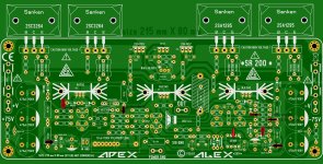
After replacing the damaged transistor. And installing the NJW's I got the below readings.
Now readings are as under.
R11 - 15 K - Measured Voltage : 15.29 VDC
R16 - 3.3 K - Measured Voltage : 0.375 VDC
R17 - 3.3 K - Measured Voltage : 0.905 VDC
But the problem is still there. I cannot change the voltage across the resistor to set the bais. Please guide me further Mr. Vzaichenko
Attachments
Hi, Sadik,
Me too had similar problems while assembling another amp.
Hope you will be able to fix the issue soon.
You are in the right lace and many excellent designers have already addressed your issues.
Let me add my 2 cents:
1.Please check the pcb traces against the correct schematic.
2. Ensure that all traces are prefect without any cracks. Some traces will be visually ok but they may have high resistance.
3. Use only one pair in the output during testing
4. Use low voltage transformers initially. I start with a 15.0.15 and gradually increase to the rated DC voltage with series bub.
5. Verify each section of the amp on pcb.
I am sure that your SR200 will start singing soon.
Thanks,
Sumesh
After replacing the damaged transistor. And installing the NJW's I got the below readings.
Now readings are as under.
R11 - 15 K - Measured Voltage : 15.29 VDC
R16 - 3.3 K - Measured Voltage : 0.375 VDC
R17 - 3.3 K - Measured Voltage : 0.905 VDC
But the problem is still there. I cannot change the voltage across the resistor to set the bais. Please guide me further Mr. Vzaichenko
Hi Sadik,
In normal operation the circuit of this kind must be symmetrically balanced.
That means, voltages actoss R25, R26, R27, R28 (0.7-0.9V) must be the same (not exactly, but within, say 20% tolerance).
Same thing with the voltages across R16, R17 (1.5-1.6V) - voltages must be similar.
If those voltages are not the same or noticeably different from the values I mentioned above - something is wrong. Broken parts, cold solders, trace cracks, unexpected shorts - there are many reasons for wrong behavior.
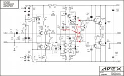
By the way - good practice is to test the frontend (IPS + VAS) separately, before connecting OPS to it. Not always straight forward, but with this particular design - pretty easy. See the drawing attached.
You need to disconnect the bias spreader and NFB connection, then solder-in a pair of 100R resistors between the VAS collectors and connect NFB point between those resistors. No load must be connected.
Now you need to check zero offsef at yout new output, and then measure the voltage across both 100R resistors to check the VAS current. For example, you measure 1.6V across both resistors in series - then:
Ivas = Vrr / (R + R) = 1.6 / (100 + 100) = 0.008 A = 8 mA
If the DC performance looks good, you can send a sine wave to the input and see an amplified sine wave at the output (still no load).
If everything looks good - remove the 100R resistors, connect the OPS and NFB back to their normal places, set the bias and voila - the amp is running.
I also strongly recommend to keep the scope connected to the output at all times durint testing - in case of unexpected oscillation you can see it right away and switch the amplifier of before the smoke and flame.
This kind of approach allows much safer testing at the first power-ons.
Cheers,
Valery
Attachments
Hi Sadik,
In normal operation the circuit of this kind must be symmetrically balanced.
That means, voltages actoss R25, R26, R27, R28 (0.7-0.9V) must be the same (not exactly, but within, say 20% tolerance).
Same thing with the voltages across R16, R17 (1.5-1.6V) - voltages must be similar.
If those voltages are not the same or noticeably different from the values I mentioned above - something is wrong. Broken parts, cold solders, trace cracks, unexpected shorts - there are many reasons for wrong behavior.
By the way - good practice is to test the frontend (IPS + VAS) separately, before connecting OPS to it. Not always straight forward, but with this particular design - pretty easy. See the drawing attached.
You need to disconnect the bias spreader and NFB connection, then solder-in a pair of 100R resistors between the VAS collectors and connect NFB point between those resistors. No load must be connected.
Now you need to check zero offsef at yout new output, and then measure the voltage across both 100R resistors to check the VAS current. For example, you measure 1.6V across both resistors in series - then:
Ivas = Vrr / (R + R) = 1.6 / (100 + 100) = 0.008 A = 8 mA
If the DC performance looks good, you can send a sine wave to the input and see an amplified sine wave at the output (still no load).
If everything looks good - remove the 100R resistors, connect the OPS and NFB back to their normal places, set the bias and voila - the amp is running.
I also strongly recommend to keep the scope connected to the output at all times durint testing - in case of unexpected oscillation you can see it right away and switch the amplifier of before the smoke and flame.
This kind of approach allows much safer testing at the first power-ons.
Cheers,
Valery
Thank you very much Sir for your guidance. But i dont have scope. I double checked if there are some cold solders, cracks or short. Every thig looks fine. I even double checked all transistors and resistors everything is fine.
I an no expert but i have one question, Can lower DC voltage be the problem? I am feeding 45 VDC per rail.
does a 18pf capacitor needed between Q9 collector ans Q2 base?
I will add this cap and see what difference it will make.
i'm waiting for resultI will add this cap and see what difference it will make.
it's better to check result with scope
i'm waiting for result
it's better to check result with scope
I did it but still same. I am still unable to change Bais Voltage
your problem is one or some parts failure another reason is maybe mistake in PCB's tracksI did it but still same. I am still unable to change Bais Voltage
What I would do in this kind of situation - test IPS+VAS separately, make sure it runs as expected.
Then test the OPS separately, make sure it runs nicely.
As soon as everything is fine - test the whole thing again.
But in general, DIY with no generator + oscillooscope is difficult.
Even something simple, based on a computer soundcard, attenuator and software (like REW) would help a lot.
I also use this device extensively (nice for quick testing):
Velleman PSGU250
Being connected via standard USB port, it turns your Windows notebook into a 2-channel oscilloscope + functional generator, able to build a Bode plot (amplitude+phase) automatically.
- Home
- Amplifiers
- Solid State
- Studio Reference Amplifier