Noise Problem
Hello everyone! I have built the Apex SR200 Amplifier using Alex MM's PCB V3.1 and it works but I have a weird problem with noise,more likely a ground problem! With no input connected,there is a loud humm from the speaker.If I approach my finger to the 10uF capacitor(the big one) the humm amplifies,if I touch the heatsing or any of the speaker wire,the noise is reduced a little but still loud! Keep in mind that the heatsink has absolutely no contact with any part or the pcb but still has an effect if I touch it! If I short the input,the amplifier goes dead silent! The only time when hum dissapear is when signal is fed in or when I short the input.If I turn off the signal sourse but still keep it connected,the noise reappears but not so loud! I powered the amplifier from a +/-50VDC,idle current is 170mA and the DC Offset is 0,8mV.All this time i used a 100W light bulb in series.Checked all the connections,checked for solder bridges,etc. all fine but I can't get rid of the noise.Can someone give me a hint of what I can do further? It's driving me nuts! Thank you in advance!
Hello everyone! I have built the Apex SR200 Amplifier using Alex MM's PCB V3.1 and it works but I have a weird problem with noise,more likely a ground problem! With no input connected,there is a loud humm from the speaker.If I approach my finger to the 10uF capacitor(the big one) the humm amplifies,if I touch the heatsing or any of the speaker wire,the noise is reduced a little but still loud! Keep in mind that the heatsink has absolutely no contact with any part or the pcb but still has an effect if I touch it! If I short the input,the amplifier goes dead silent! The only time when hum dissapear is when signal is fed in or when I short the input.If I turn off the signal sourse but still keep it connected,the noise reappears but not so loud! I powered the amplifier from a +/-50VDC,idle current is 170mA and the DC Offset is 0,8mV.All this time i used a 100W light bulb in series.Checked all the connections,checked for solder bridges,etc. all fine but I can't get rid of the noise.Can someone give me a hint of what I can do further? It's driving me nuts! Thank you in advance!
Hi Atelierul29,
Silly question: did you try playing some music without the series 100W bulb? (could it only be 100Hz supply voltage ripple?)
hopre this helps.
Silly question: did you try playing some music without the series 100W bulb? (could it only be 100Hz supply voltage ripple?)
hopre this helps.
An externally hosted image should be here but it was not working when we last tested it.
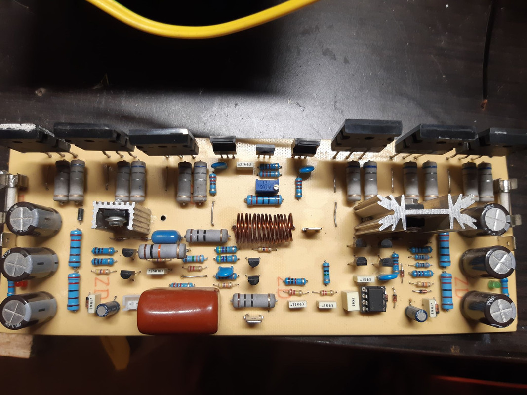
Here's the PCB that I used! My build is exactly the same,down to the smallest part! That 10uF capacitor is very sensitive to hum! If I approach my hand towards it,the hum gets very loud!No I didn't tried it but it can't be the supply! The hum goes away if I short the input or if I connect a signal to it! If it would be supply ripple I guess it must be always present but it's not! The hum is very present when nothing is connected to input!Hi Atelierul29,
Silly question: did you try playing some music without the series 100W bulb? (could it only be 100Hz supply voltage ripple?)
hopre this helps.
If the hum goes away with a shorted input, or a real signal source, then it is just RF pickup from something nearby. I wouldnt worry about it, especially if it's just a bare board on your desk
Now I can't get a reading on the 0,33 ohm resistors!Nothing happens when i turn the pot in any direction.Can't adjust the bias!
Whats the value of trimmer that you are using for setting the Bias Voltage. Please share the photo of PCB also. I cannot see the photo of your PCB.
Last edited:
Trimmer is 1k multiturn! You can see the PCB i used below and also my build! For parts I used exactly the same values as the silkscreen. I checked BD139 and is ok,checked the voltage on R11 and it's 15V,checked the voltage on the zenners and it's 15V.I get 0mV reading on the 0,33R,the amp is stone cold and sounds weak....like a 20...30W one and with little bass!There is also a strong hum when nothing is conected to input but I think this is fixable.Please,help me! I like this amplifier so much and I don't want to see it go to the failiure box!

How did you solve it?At last its working. The problem is solved. I must say this is one of the best amp in its class.
I have set about 24.4 mV across the 0.68ohms x 2 (parallel) resistors. I hope this is fine. Now i need to find the PCB of regulated Power supply which can feed both my channels. Can someone guide me to the post number where I can find the PCB for itching with help of toner transfer method.
It seems no one can help me! In the mean time I did some measurements as follows:
R25,26,27,28=0,839V
R11=14,84V
R16,17=1,5V
On 0,33R(0,68r pair) I have 0 mV
Checked the voltage on zenners=15V
Checked BD139 and is OK
VBE on output transistors is about200mV
1k pot still does nothing
R25,26,27,28,11,16,17 and zenners looks ok but the rest I can't explain myself
R25,26,27,28=0,839V
R11=14,84V
R16,17=1,5V
On 0,33R(0,68r pair) I have 0 mV
Checked the voltage on zenners=15V
Checked BD139 and is OK
VBE on output transistors is about200mV
1k pot still does nothing
R25,26,27,28,11,16,17 and zenners looks ok but the rest I can't explain myself
1st check bd 139 emmitor to collector. 2nd set Multimeter 2 volt and just checked npn and PNP base- to collector .volt up down..when u moving trim pot
How i solved my problem
In first place I got the PCB's made professionally form JLC. I also replaced the BC560C transistors with BC556B, because i doubt the 560C which i have are fakes. I also had doubt that the 2N5401 transistors, so i got new stock from a trusted online store and replaced them too. I also changed the value of 1K resistor to 1.5K the one which is exact below the BD139 transistor.
I would suggest you to get the small transistors from a genuine seller like rs-components or mouser or element14
How did you solve it?
In first place I got the PCB's made professionally form JLC. I also replaced the BC560C transistors with BC556B, because i doubt the 560C which i have are fakes. I also had doubt that the 2N5401 transistors, so i got new stock from a trusted online store and replaced them too. I also changed the value of 1K resistor to 1.5K the one which is exact below the BD139 transistor.
I would suggest you to get the small transistors from a genuine seller like rs-components or mouser or element14

Thank you for your response! I think I managed to change something but on my other module which is not on a heatsink.Checked all the voltages mentioned above,checked absolutely all transistors and all are good! In fact,i managed to destroy a 2SA1837 in the process! Placed a 10R/10W resistors instead of fuse and connected a multimeter across it.Now,when I turn the pot,the voltage changes,not like before.But it's not stable,I think because there's no heatsink.Anyway,now I can see that transistors are warming up,when I turn the pot,that's a good thing.I'll move on the other module with the heatsink and see if I can revive it too! I will come back with conclusions and pictures.I still need to fix the hum issue!
You mention you don’t have a heatsink!!!
Without a heatsink you may not have already blown up an output, but you have surely stressed it too much.
Always attach the heatsink before any type or power is given to the amp board.
Without a heatsink you may not have already blown up an output, but you have surely stressed it too much.
Always attach the heatsink before any type or power is given to the amp board.
Thank you for your concern! I know the rule but this is not the first amp that I test it this way,if you move fast and watch the bulb,nothing will happen! In fact,I did managed to blow a trace on one of the PCB's...the heatsink one...my test resistor fell and touched the LED trace! Changed the LED and the thing is back in action! I also found the culprit that didn't let me adjust the bias.Turns out that both of my multiturn resistors,were changing value only in one direction! Now I can set the bias.For now it's at 20mV across 0,33 ohms resistors.I will go higher but now I must solve the hum problem when no signal is fed in! Any idea on how to get rid of it?Or why it's present only when no signal is fed in? With signal,the amp is dead silent,also If I short the input the amp goes dead silent!
Hi everybody,
referring to #2948, I would like to know where I can find the schematic of that pcb.
Thank you so much,
Marco
referring to #2948, I would like to know where I can find the schematic of that pcb.
Thank you so much,
Marco
- Home
- Amplifiers
- Solid State
- Studio Reference Amplifier