Hi InOtIn,
A slight change was made to the port label names some time ago. The current names are as given in the Help file:
Ap - Vented rear chamber port cross-sectional area (sq cm).
Lpt - Vented rear chamber port tube length (cm).
Ap1 - Throat port or throat adaptor entry cross-sectional area (sq cm).
Lp - Throat chamber port or throat adaptor length (cm).
Kind regards,
David
Thank you, David - that explains it
")
What starting value should be used to calculate the local flare rate for a 1" CD? Candidates are 2.53cm2, 3.226cm2 and 5.067cm2.
Still looking for a definitive answer to this.
In the meantime, I would also appreciate if someone could point out to me where I go wrong in calculating the flare rate for the 1" CD in Hornresp, because it doesn't look right to me.
This is how I've tried to go about it so far, step-by-step:
1. Starting with a CoSyne-based 80H x 40V conical horn holding directivity to 300Hz.


2. Double-click S1 to bring up:

3. Click to calculate L12 instead of Fta:

4. Amend S2 to double that of S1:

5. Click calculate to get L12 (in this case 0.59):

6. Click save to return to input parameter window:

7. Highlight Con12 (0.59), hit "E" key to change from conical to exponential, and read flare rate in F12, as circled below:

... which doesn't look right (too high) for this 80 x 40 horn. Using different S1 doesn't change this fact:


What am I doing wrong...?
???
Why are you changing to exponential? I don't think you have or want an exponential expansion there near the throat do you?
BTW, my suggestion in the spreadsheet to use a 0.707x0.707 square as the initial throat is because I planned to then open it to a 1"D circular throat with a drill. My cheap'n'easy way to repeatably transition from a round throated driver to a rectangular horn, so the throat actually starts as a 1"D circle. No idea if that scheme is ideal, but the other easy option was to start with a 1"x1" square and then use wood putty to smooth that down into a circular throat, which wouldn't be as repeatable. I made horns both way, can't say either worked any better or really much different than the other. Contrary to lots of reports I've read, smallish changes down there never seemed to make a big difference in measured response. I've also considered doing it the way Danley did, and just have the throat be the circular hole of the compression driver mounted on a square entry to the horn ("getting the diffraction over with" was I think how he stated it in a response to a post by Geddes), but haven't actually tried that one.
Also, my usual strategy of getting the mid entry as close as possible to the throat may not be technically correct, but as my waveguides were always wide angled (usually 90 degrees) and my compression tweeters small (usually CDX1-1445, which doesn't go much below 2kHz easily), the best place for a highish crossover always wanted to be closer to the tweeter than I could get it. With a narrower conical horn (longer, with slower expansion) or with a tweeter that pushes lower, then the best place could well be further up from the throat.
Also, I wouldn't recommend putting too much effort into getting a linear-phase (square wave reproducing) response from the physical horn. It's not easy to do, takes a ton of crossover components and is nowhere near as smooth or linear in phase as you can get using a FIR equalizer such as OpenDRC (I ended up adding that to mine. Just get a good response with good coverage and then fix it (if linear phase is important to you) with the FIR dsp afterwards.
Just to be clear - 5cm2 is the correct value for S1. That is the area of the 1" dia circle you end up with when you do as Bill says and drill out the initial .707" square.
I agree that the flare rate is confusing. Long back I asked for a theoretical/mathematical explanation and got that step by step procedure for getting HR to calculate it for you. What should be pointed out however is that once you have the HR plotted frequency response of the mids on the horn, you don't need the flare rate. You can see how low they will play. Just for grins, do a sim with a 2x longer L12 and correspondingly larger S2. The mids should play lower but not as high. Just another compromise you will be forced to deal with if you design a synergy horn. The low limit is determined by the flare rate at the entry point; the high limit by the round trip time for the reflection from the CD diaphragm, both together with the driver characteristics. To get an accurate reading of the latter, you need to add the acoustic path length of the CD to the L12 of the horn itself to get a total L12 for HR to crunch on.
While playing what-if games on teh simulator, you can change the first segment from CON to EXP and see that it doesn't change the response much. Where you will see big changes is changing the chamber type to throat ported (if it isn't already) and then playing with port length and area, Vtc, and Atc. These take a lot of optimization and some cut and try is inevitable no matter how much HR simulation you do.
good luck!
Thanks for replying and apologies if I'm being a bit thick - but I have read the patent a few times, as well as this and other synergy threads, and from what I've taken away so far is that the first of these statements, in relation to mid port location, is in accordance with the patent while the second statement seems to say the exact opposite of the first, no?
I'm a bit late to the Synergy game but I'm excited to dive straight in and get my feet wet - just need to get my facts straight first, so please bear with me while I'm trying to do so.
No, one addresses where the mid should tap in for horn loading, and the other addresses where the compression driver unloads and where the midrange ports will no interfere with the compression driver's frequency response. Those are not the same point. There should be a gap in the two frequency ranges because they will sum together and result in a flat response.
I'm a bit late to the Synergy game but I'm excited to dive straight in and get my feet wet - just need to get my facts straight first, so please bear with me while I'm trying to do so.
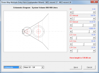
Suggest you use the Multiple Entry Horn Wizard to simulate the whole system, not just the midrange component. See the Hornresp Help file for details.
Attachments
Here's a crazy thought: Given a square horn, and four identical midranges in series/parallel, what would happen if the mids are placed in the four corners of the horn, but the entry port of two of them, in opposing positions, are placed somewhat further from the entry than the other two (offset less that 1/4 wavelength of the mid/high crossover). Would this extend the frequency range covered by the mids?
I can imagine that the impedance plot would be interesting. And I can't imagine that it could be simulated with the present tools. But as a mind experiment?
Sheldon
I can imagine that the impedance plot would be interesting. And I can't imagine that it could be simulated with the present tools. But as a mind experiment?
Sheldon
Sheldon,Here's a crazy thought: Given a square horn, and four identical midranges in series/parallel, what would happen if the mids are placed in the four corners of the horn, but the entry port of two of them, in opposing positions, are placed somewhat further from the entry than the other two (offset less that 1/4 wavelength of the mid/high crossover). Would this extend the frequency range covered by the mids?
No, it would not extend the frequency range covered by the mids.


Finally got to a point where I could listen to the speaker. Still very far from finished. The buyout Titan drivers work decently. Only put 2 of 4 on so far, but I was eager to have a listen. After some time doing EQ, it sounds quite good. I'm sure I could get it flatter than shown if I used the rest of the PEQs, but that would probably be a waste of time.
I will have to do a lot of experimentation with the mid chambers. They're currently flat out to 800hz, but I'm hoping that by shaping the ports and reducing the chamber volume I can get them up to a more reasonable crossover point like 1.6k or higher.
If I can't get them high enough to not strain the D220Ti, might buy some Eminence PSD:2002s and put the Seleniums on a different project.
Z-
It looks like your midrange is already more sensitive than your tweeter, I'm not sure I'd bother adding more mid drivers (after all, the midrange ports aren't a good thing, from the tweeter's perspective). I'm pretty sure you can pull the mid's HF out further by adding frustrums (tapered openings) to the ports and, as you said, by filling the volume in some. Wood putty works pretty well for that, plumber's putty or modeling clay will work for testing (since they don't harden and can be easily adjusted)
edit: I hadn't notice the scale on your plot is only 2B per..... that's a more-than-decent result there on flatness.
Last edited:
I used some very low cost GRS mids, which only cost about $1 more than the Titans. They should be very similar (cheap, no frills, oem'ish)
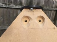
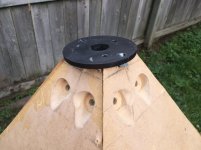
I did this with a dremel tool. I might still try to fill in the area between the cone and horn to raise the freq resp and increase the overlap with the CD.
Here is a link to my build:
http://www.diyaudio.com/forums/mult...-bandpass-mid-unity-horn-193.html#post4354601
I did this with a dremel tool. I might still try to fill in the area between the cone and horn to raise the freq resp and increase the overlap with the CD.
Here is a link to my build:
http://www.diyaudio.com/forums/mult...-bandpass-mid-unity-horn-193.html#post4354601
Attachments
Last edited:
What HIPCHECK has shown is basically what I intend to do. The mids roll off at 250 currently, which is much lower than the ~400ish I was planning to design to. I'm basically hoping to shift the entire bandpass section up nearly an octave by including frustrums to the ports and cone volume fill.
As for the frequency response, it does look nice but uses EQ to achieve it. There is also no proper electrical crossover at work. I've just highpassed both drivers well below the passband for protection and let them hand off acoustically. The mids require +8.5db of boost to match the sensitivity of the CD.
The ultimate goal of this is for parties where mostly EDM and bass music will be played. I think the additional 2 mids will be needed. I actually bought 6 for each side, but I figured it would force the taps too far away from the CD to cross over high enough.
Synergy horns are intimidating, but I gotta say it's pretty amazing how easy it is to get a good result with even the cheapest components and a bit of DSP. I'll admit I spent a lot of time reading about how to get the mids right since they're really the heart of the synergy, but in the end I didn't even bother doing sims. Just took a 1/2" drill to about where I thought they should go and screwed them on. lol
Hello,
if you work on getting everything smoothed out, sanded, and shaped that will help a bunch. The cheap kids are the weakest link in my build. I have 4 and they are still down to the CD driver in SPL. Use the extra drivers to get up there SPL wise as the boost is most likely killing off the lower distortion benefits we are looking for in this build. 4 drivers, horn loaded, and band passed (crossover and by synergy design) is what you want!
Also, the high end raggedness will smooth out when the crossover is dialed in. The large overlap you are using now is the culprit for much of that. The first one I built ( before making it 3 way) I just tossed a 1500 he crossover on both drivers (12db IIRC) and played it. There were several peaks/nulls when I finally measured it. I fixed with EQ then but last time I played with this design I work out a much better crossover for it.
I am trying to make a passive design for mine now.
Steve
New sealed back drivers from Beyma - Synergy candidates?
Hi,
I have just come across these two new sealed back drivers from Beyma (see attached files). They look like potential candidates for some all-out no-compromise Synergy horns.
The new Beyma drivers are not exactly cheap, and I understand that a real advantage of the Synergy concept is that you may not need using expensive drivers if the design is well thought out. However, I cannot help thinking that if you go through all the work of simulating, designing and actually building a pair, then it could be interesting to see how far you could take the concept if you used some of the best drivers out there....
Best regards
Peter
Hi,
I have just come across these two new sealed back drivers from Beyma (see attached files). They look like potential candidates for some all-out no-compromise Synergy horns
. The new Beyma drivers are not exactly cheap, and I understand that a real advantage of the Synergy concept is that you may not need using expensive drivers if the design is well thought out. However, I cannot help thinking that if you go through all the work of simulating, designing and actually building a pair, then it could be interesting to see how far you could take the concept if you used some of the best drivers out there....
Best regards
Peter
Attachments
Those are very cool drivers, but I wonder if even being extremely high quality there is a limit to the benefits you could get in a synergy horn. The band-passes limit distortion so there may not be much to gain there. And at some point, even with medium quality pro drivers, I imagine you may start to achieve SPLs so high that air nonlinearity may become a distortion issue.
And I would never mistake high price for high quality. It's a fact in marketing that if you price a non-commodity item too low, it won't sell! And a corollary is that if you pay more for something you could easily only be paying for the markup that was created to establish a "perceived value". Look at performance and consistency, NEVER price.
2nd Horn Flare discussion?
Hello,
I have a question about the second horn flare in a Synergy horn that does not require a new thread.
My horn has been built for some time and waiting on me to decide weather I wanted to add a second flare before I built the out shell/box. I plan to listen to this speaker 80% indoors and host a few small events/bands/BBQ outdoors. What ratio of the first horn section is ideal for indoors and what ratio of second horn section is the lowest amount needed to achieve any effects. I know several builds have just the one horn flare (for example to SynTripP horn). I would like to just build the box and enjoy the speaker, but I am considering more construction to build the second horn flare.
The biggest issue is they are already just a bit big to hide from the WAF in the living room! I know I am in good hands with you guys! I built them as big as I could to get pattern control as low as possible in room.
Steve
I think the primary benefit of the 2ndry flare is to eliminate pattern narrowing with frequency just before the horn loses pattern control. I doubt you care about that indoors as you'll not likely have any seats affected by that narrowing. Outdoors at events pattern narrowing would be a problem.
A second affect is mouth reflections. I see more problems with mouth reflections in simulation with a secondary flare than without. OTOH, even a baffle termination increases mouth reflections in simulation. I have a partial baffle in my corner horn but I don't see the mouth reflections from it in my measurements. Its still early in the game for me there. Theory wise (someone correct me if I'm wrong) a conical horn doesn't suffer from mouth reflections like an exponential horn. Keele's paper in which he popularized a 2ndry flare was about a combined exponential & conical horn. That isn't what most of us are building. You see at most small 2ndry flares on Danley Synergies.
A third affect is increased pattern control, assuming the 2ndry flare is added on as opposed to a new design that keeps the same mouth size but gets there in two stages. Increased vertical pattern control might be a benefit indoors, in reducing floor and ceiling flections, but you are likely to need some form of treatment anyway.
Then there is the WAF, My corner horn is supposed to hide in plain sight. There is no way it can do that with a large 2ndry flare hanging on to its front.
edit: its not mouth reflections due to the secondary flare; its reflection from where the primary and secondary flares meet. Reference the Charles Hughes "Quadratic Throat Waveguide" paper where he recommends foam lining at the mouth of the horn instead of a secondary flare (in addition to a quadratic throat)
- Home
- Loudspeakers
- Multi-Way
- Suitable midrange cone, for bandpass mid in Unity horn.