I just got one of the updated boards. Not happy. The changes to my board were clearly made after the original fabrication and done very sloppily. Flux all over, sloppy solder joints, two cold joints, one lead bent over until it touches the one next to it. Yuck ...
Worse, though, is that the capacitors used to replace R12,13,16,17 are tiny little monolithic ceramics.Not the kind of thing you want to see in the signal path. They're under the daughterboard, so there's no space for anything bigger and no way to get to them to replace. Ugh
Just an update to say that Sure refunded my money on the board. The sloppy modifications had left a blob of solder on one RCA jack that made it impossible to attach a cable, so only 3 channels were usable. It looks like the original manufacture of the board was solid, and the customer service was good, but the modifications were/are a problem.

2x100
http://www.diyaudio.com/forums/class-d/143669-sure-electronics-new-tripath-board-tc2000-tp2050.html
If that one blows up you may want to go with the Sure 2X100. More room to mod and we have had no trouble with those since they went to the fan cooling.My replacement modified board has arrived. a good sign is that there was no smoke on power up! I hope to be able to test it properly in the next couple of days. Sure have been very good, despite the issues. If I have no joy with this then I do not know what to do next.
An externally hosted image should be here but it was not working when we last tested it.
http://www.diyaudio.com/forums/class-d/143669-sure-electronics-new-tripath-board-tc2000-tp2050.html
Hi Scott. I would have gone for the other boards but for cost. I was undecided for some time but went with the four channel when it came out. I may well ask sure to send me two, and refund this in part payment if it doesn't work when I test it properly this week. Sure have been great, even if it I have been waiting a while. I would not hesitate to use them again just on customer service alone.
I have always liked the Tripath sound, having enjoyed a Trends for a while (why I ever sold it I will never know..) but I also like the chip amps I have heard too.
Steve
I have always liked the Tripath sound, having enjoyed a Trends for a while (why I ever sold it I will never know..) but I also like the chip amps I have heard too.
Steve
Last edited:
DC Offset issues
I have been following this Forum for a while now, and finally took the jump and went from a topping tp-10 mk3 to this 4x100w board, with the intention of using it in a bi-amp setup CH1+CH2 for the Left CH3+CH4 for the right.
I have hooked it up to a 24v 14.6A power supply via the terminal blocks and have given it a quick test, all appears to be working correctly and i could hear my source. however my Speaker cone's (kef q3) were visibly resting forwards of their usual resting point (both with a source connected and disconnected). After testing with a multimeter i found these to be the DC offsets (no source connected):
CH1 333mv
CH2 288mv
CH3 -482mv
CH4 136mv
I then tried to adjust these offsets using the trimmers under the heat sink, however the figures were only getting higher (worse).
So my question really is, could i have done (or not done something) something to make these figures be so high? as sure suggest these figures should be under 10mv. Can something be done to correct this offset without sending the board back? my soldering skills are at best - awful!
Many Thanks,
Craig
Hi audio1st,
Thank you for your quick reply!
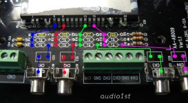
I have found R6 and R7 (under the heat sink) I guess R8 and R9 are under the daughter board, however R6 and R7 just look like solder is bridging the connections, so I presume that the resistors have been removed, unless I am looking at the wrong resistors?
Is there anything else I could have done incorrectly? I have adjusted the trim pots which has improved the Offset slightly but only by a few mv at best.
Many Thanks,
Craig
Thank you for your quick reply!
I have found R6 and R7 (under the heat sink) I guess R8 and R9 are under the daughter board, however R6 and R7 just look like solder is bridging the connections, so I presume that the resistors have been removed, unless I am looking at the wrong resistors?
Is there anything else I could have done incorrectly? I have adjusted the trim pots which has improved the Offset slightly but only by a few mv at best.
Many Thanks,
Craig
Can anyone summarize the most important mods to make to this board? Any resistors, capacitors, or inductors to remove or upgrade?
I hooked one up to a meanwell 350, to "bi-amp" two Usher S-520's. Sounds pretty awesome to my ears. Just feeding it from the headphone output of my PC into a headphone splitter.
I wish there were a cheap but good DAC board I could use to feed it digital audio over USB, instead of relying on the Realtek 889 sound chip on my motherboard.
Craig, Audio1st, I set my multimeter to 2000m DCV. I unplugged the input into the board. I put the probes on each of the 4 pairs of screws that drive the speaker outputs. I measured 312, 278, 174, -42. Assuming I did that correctly, I wonder if those results are bad. I wonder if other people are getting results like Craig and I. As an aside, I measure my Meanwell delivering 20.5 V at the screws where it ties into the Sure. I have a fairly new board, shipped out just a month ago. Should I unscrew and twist off the heatsink, so I can have a look see at my R6-R9, and I tweak what I assume will be 4 trim pots under there?
Craig, Audio1st, I set my multimeter to 2000m DCV. I unplugged the input into the board. I put the probes on each of the 4 pairs of screws that drive the speaker outputs. I measured 312, 278, 174, -42. Assuming I did that correctly, I wonder if those results are bad. I wonder if other people are getting results like Craig and I. As an aside, I measure my Meanwell delivering 20.5 V at the screws where it ties into the Sure. I have a fairly new board, shipped out just a month ago. Should I unscrew and twist off the heatsink, so I can have a look see at my R6-R9, and I tweak what I assume will be 4 trim pots under there?
Not just you guys. My board gives:
179mV
-50mV
143mV
-296mV
That's just connected to a 12v/20W wall wart, as I don't have the connectors for my 24v SMPS wired up yet.
I wonder if the DC offset was tuned out w/ the 100k resistors to ground, but wasn't tweaked after they were removed. Or -- worse -- maybe the circuit was built around the 100k resistors, and it's no longer possible to tune out the DC without them? Hmm ...
Anybody know if it's safe to run the chips w/o the heatsink so long as there are no input signals? Otherwise, to try to adjust the offset, I guess I need to find a smaller, temporary heat sink just to keep them cool and let me reach the pots.
When checking for DC offset, don't you short the input to ground?
Wachara C.
My board gives the same offset whether input is shorted to ground or not.
Not just you guys. My board gives:
179mV
-50mV
143mV
-296mV
That's just connected to a 12v/20W wall wart, as I don't have the connectors for my 24v SMPS wired up yet.
I wonder if the DC offset was tuned out w/ the 100k resistors to ground, but wasn't tweaked after they were removed. Or -- worse -- maybe the circuit was built around the 100k resistors, and it's no longer possible to tune out the DC without them? Hmm ...
Anybody know if it's safe to run the chips w/o the heatsink so long as there are no input signals? Otherwise, to try to adjust the offset, I guess I need to find a smaller, temporary heat sink just to keep them cool and let me reach the pots.
I think the DC offset would change somewhat with temperature also.
With these DC offset values, have you played music using the amp anyway?
Wachara C.
I think the DC offset would change somewhat with temperature also.
With these DC offset values, have you played music using the amp anyway?
Wachara C.
I hooked it up to some cheapie bookshelf speakers. Enough to say that, yes, it played music, but not enough to tell the quality.
I hooked it up to some cheapie bookshelf speakers. Enough to say that, yes, it played music, but not enough to tell the quality.
I just received mine this morning, and I'll try it tonight. I will also make some measurements and report back.
Wachara C.
- Status
- This old topic is closed. If you want to reopen this topic, contact a moderator using the "Report Post" button.
- Home
- Amplifiers
- Class D
- Sure Electronics New Tripath Board 4*100W class-D Amplifier Board